Pipelining What Seymour Cray taught the laundry industry


- Slides: 22

Pipelining What Seymour Cray taught the laundry industry 1. Pipelining 2. Parallelism 3. Interleaving Quiz 2 will cover material through THIS lecture Handouts: Lecture Slides 1

Forget circuits for a while … INPUT: dirty laundry Device: Washer Function: Fill, Agitate, Spin Washer. PD = 30 mins OUTPUT: 6 more weeks of clean clothes Device: Dryer Function: Heat, Spin Dryer. PD = 60 mins 2

One load at a time • Why do MIT students put off doing laundry? Step 1: Step 2: • The fact is, doing one load at a time is not smart. Total = Washer. PD + Dryer. PD 90 = _____ mins 3

Doing N loads of laundry • Here’s how they do laundry at Harvard, the “combinational” way. Step 1: Step 2: Step 3: Step 4: … Total = N*(Washer. PD + Dryer. PD) N*90 = ______ mins 4

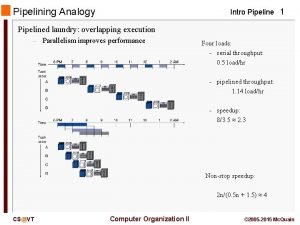
Doing N Loads… the MIT way • MIT students “pipeline” the laundry process. • That’s why we wait! Actually, it’s more like N*60 + 30 if we account for the startup transient correctly. When doing pipeline analysis, we’re mostly interested in the “steady state” where we assume we have an infinite supply of inputs. Step 1: 30 Step 2: Step 3: … +60 Total = N * Max(Washer. PD, Dryer. PD) N*60 = ______ mins 5

Performance Measures Latency: The delay from when an input is established until the output associated with that input becomes valid. 90 (Harvard Laundry = _____ mins) 120 ( MIT Laundry = _____ mins) Throughput: Assuming that the wash is started as soon as possible and waits (wet) in the washer until dryer is available. The rate of which inputs or outputs are processed. 1/90 (Harvard Laundry = _____ outputs/min) 1/60 ( MIT Laundry = _____ outputs/min) 6

Okay, back to circuits… For combinational logic: latency = tpd, throughput = 1/tpd. F X H G P(X) We can’t get the answer faster, but are we making effective use of our hardware at all times? X F(X) G(X) P(X) F & G are “idle”, just holding their outputs stable while H performs its computation 7

Pipelined Circuits use registers to hold H’s input stable! F 15 X H 25 G 20 P(X) Now F & G can be working on input Xi+1 while H is performing its computation on Xi. We’ve created a 2 -stage pipeline: if we have a valid input X during clock cycle j, P(X) is valid during clock j+2. Suppose F, G, H have propagation delays of 15, 20, 25 ns and we are using ideal zero-delay registers: unpipelined 2 -stage pipeline latency 45 ______ throughput 1/45 ______ 8

Pipeline Diagrams Clock cycle F 15 X H 25 P(X) i i+1 i+2 Xi Xi+1 Xi+2 i+3 G Pipeline stages 20 Input Xi+3 F Reg F(Xi) G Reg G(Xi) G(Xi+1) G(Xi+2) H Reg F(Xi+1) F(Xi+2) … … H(Xi) H(Xi+1) H(Xi+2) The results associated with a particular set of input data moves diagonally through the diagram, progressing through one pipeline stage each clock cycle. 9

Pipeline Conventions DEFINITION: A K-Stage Pipeline (“K-pipeline”) is an acyclic circuit having exactly K registers on every path from an input to an output. A COMBINATIONAL CIRCUIT is thus an 0 -stage pipeline. CONVENTION: Every pipeline stage, hence every K-Stage pipeline, has a register on its OUTPUT (not on its input). ALWAYS: The CLOCK common to all registers must have a period sufficient to cover propagation over combinational paths PLUS (input) register tpd PLUS (output) register tsetup. The LATENCY of a K-pipeline is K times the period of the clock common to all registers. The THROUGHPUT of a K-pipeline is the frequency of the clock. 10

Ill-formed pipelines Consider a BAD job of pipelining: A X Y C 1 2 B For what value of K is the following circuit a K-Pipeline? Problem: Successive inputs get mixed: e. g. , B(A(Xi+1), Yi). This happened because some paths from inputs to outputs have 2 registers, and some have only 1! This CAN’T HAPPEN on a well-formed K pipeline! 11

A pipelining methodology Step 1: Draw a line that crosses every output in the circuit, and mark the endpoints as terminal points. Step 2: Continue to draw new lines between the terminal points across various circuit connections, ensuring that every connection crosses each line in the same direction. These lines demarcate pipeline stages. Adding a pipeline register at every point where a separating line crosses a connection will always generate a valid pipeline. STRATEGY: Focus your attention on placing pipelining registers around the slowest circuit elements (BOTTLENECKS). INPUTS A 4 n. S B 3 n. S OUTPUTS C 8 n. S D 4 n. S F 5 n. S E 2 n. S T = 1/8 ns L = 24 ns 12

Pipelining Summary • Advantages: – Allows us to increase throughput, by breaking up long combinational paths and (hence) increasing clock frequency • Disadvantages: – May increase latency. . . – Only as good as the weakest link: slowest step constrains system throughput. This bottleneck is the only problem • Isn’t there a way around this “weak link” problem? 13

Eliminating Bottlenecks 4 3 2 1 A’ (2 -pipe) X C 1 Y B 1 4 -stage pipeline, throughput=1 Pipelined systems can be hierarchical: • Replacing a slow combinational component with a kpipeline version may increase clock frequency • Must account for new pipeline stages in our plan 14

How do 6. 004 Aces do Laundry? Step 1: • They work around the bottleneck. First, they find a place with twice as many dryers as washers. Step 2: Step 3: Step 4: • Throughput = loads/min ______ • Latency = ______ mins/load 15

Back to our bottleneck. . . Recall our earlier example. . . • C – the slowest component – limits clock period to 8 ns. A 4 n. S B 3 n. S C 8 n. S D 4 n. S • HENCE throughput limited to 1/8 ns. F 5 n. S E 2 n. S T = 1/8 ns L = 24 ns We could improve throughput by Finding a pipelined version of C; OR interleaving multiple copies of C! 16

Circuit Interleaving • We can simulate a pipelined version of a slow component by replicating the critical element and alternate inputs between the various copies. This is a simple 2 -state FSM that alternates between 0 and 1 on each clock Xi DQ G DQ F C 0 1 C(Xi-2) C 1 0 C’ clk F 17

Circuit Interleaving When Q is 1 the lower path is combinational (the latch is open), yet the output of the upper path will be enabled onto the input of the output register ready for the NEXT clock edge. Xi DQ G C 0 1 C(Xi-2) C 1 0 DQ C’ “It acts like a 2 -stage pipeline” Meanwhile, the other latch maintains the input from the last clock. clk Q Codd C 1 output Mux output Ceven Codd 18

Circuit Interleaving • 2 -Clock Martinizing • “In by ti, out by ti+2” N-way interleaving is equivalent to N pipeline Stages N-1 registers … N-way interleave X 3210 i DQ G x 0 1 DQ G C 0 1 C(X 10 i-2) ) C 1 0 DQ 0 1 x C’ Latency = 2 clocks • Clock period 0: X 0 presented at input, propagates thru upper latch, C 0. • Clock period 1: X 1 presented at input, propagates thru lower latch, C 1. C 0(X 0) propagates to register inputs. • Clock period 2: X 2 presented at input, propagates thru upper latch, C. C 0(X 0) loaded into register, appears at output. 19

Combining techniques We can combine interleaving and pipelining. Here, C’ interleaves two C elements with a propagation delay of 8 n. S. The resulting C’ circuit has a throughput of 1/4 n. S, and latency of 8 n. S. This can be considered as an extra pipelining stage that passes through the middle of the C’ module. One of our separation lines must pass through this pipeline stage. By combining interleaving with pipelining we move the bottleneck from the C element to the F element. A 4 n. S B 3 n. S C’ 2 x 4 n. S D 4 n. S F 5 n. S E 2 n. S T = 1/5 ns L = 25 ns 20

And a little parallelism… Step 1: We can combine interleaving and pipelining with parallelism. Step 2: Throughput = 1/15 load/min _2/30 _ =_____ Step 3: 90 Latency = _______ min Step 4: Step 5: 21

Next Time: Programmable Machines Dilbert : S. Adams 22
 Par stock linen
 Donna seymour
 Pass and seymour arc fault receptacle
 Kelly hoppen facts
 Under the bleachers by seymour butz
 Seymour house dundee
 William seymour miracles
 Mike seymour manchester
 Elementary data organization in data structure
 Geriatric giants
 St mary cray primary
 Graham cray
 Vector supercomputer
 Graham cray
 Cray 1 architecture
 Cray-xmp-144
 Which feeding level represents the primary consumers
 St mary cray primary school
 Cray 1
 John levesque cray
 Adam smith pipelining
 Pipelining and superscalar techniques
 Pipeline arsitektur komputer
