PDT 202 HEAT TRANSFER CHAPTER 7 HEAT EXCHANGERS
 Prepared by: Dr. Tan")
 • Perform a general energy analysis on heat exchangers. • Obtain")


- Slides: 38
PDT 202: HEAT TRANSFER CHAPTER 7: HEAT EXCHANGERS (LECTURE 2) Prepared by: Dr. Tan Soo Jin
Learning Outcomes (LO) • Perform a general energy analysis on heat exchangers. • Obtain a relation for the logarithmic mean temperature difference for use in the LMTD method, and modify it for different types of heat exchangers using the correction factor. • Develop relations for effectiveness, and analyze heat exchangers when outlet temperatures are not known using the effectiveness-NTU method. • Know the primary considerations in the selection of heat exchangers.
Analysis of Heat Exchangers An engineer often finds himself or herself in a position 1. to select a heat exchanger that will achieve a specified temperature change in a fluid stream of known mass flow rate – the log mean temperature difference (or LMTD) method. 2. to predict the outlet temperatures of the hot and cold fluid streams in a specified heat exchanger – the effectiveness-NTU method. 1 st Law thermodynamics requires the rate of heat transfer from the hot fluid be equal to the cold one. Heat capacity rate Two fluid streams that have the same capacity rates experience the same temperature change in a well-insulated heat exchanger.
Analysis of Heat Exchangers Variation of fluid temperatures in a heat exchanger when one of the fluids condenses or boils.
The Log Mean Temperature Difference Method log mean temperature difference Variation of the fluid temperatures in a parallel-flow doublepipe heat exchanger.
Parallel-flow and Counter Flow Heat Exchangers Arithmetic mean temperature difference: • The logarithmic mean temperature difference Tlm is an exact representation of the average temperature difference between the hot and cold fluids. • Note that Tlm is always less than Tam. Therefore, using Tam in calculations instead of Tlm will overestimate the rate of heat transfer in a heat exchanger between the two fluids. • When T 1 differs from T 2 by no more than 40 percent, the error in using the arithmetic mean temperature difference is less than 1 percent. But the error increases to undesirable levels when T 1 differs from T 2 by greater amounts.
Counter-Flow Heat Exchangers • In the limiting case, the cold fluid will be heated to the inlet temperature of the hot fluid. • However, the outlet temperature of the cold fluid can never exceed the inlet temperature of the hot fluid. • For specified inlet and outlet temperatures, the Tlm for a counter-flow heat exchanger is always greater than that for a parallel-flow heat exchanger. • That is, Tlm, CF > Tlm, PF, and thus a smaller surface area (and thus a smaller heat exchanger) is needed to achieve a specified heat transfer rate in a counter-flow heat exchanger. When the heat capacity rates of the two fluids are equal
Multipass and Cross-Flow Heat Exchangers: Use of a Correction Factor • The correction factor F depends on the geometry of the heat exchanger and the inlet and outlet temperatures of the hot and cold fluid streams. • F for common cross-flow and shell-andtube heat exchanger configurations is given in Fig. 11 -18 versus two temperature ratios P and R defined as 1 and 2: inlet and outlet T and t: shell- and tube-side temperatures F = 1 for a condenser or boiler
Fig. 11 -18 Correction factor F charts for common shell-and -tube heat exchangers.
Fig. 11 -18 Correction factor F charts for common shell-and -tube heat exchangers.
The Log Mean Temperature Difference Method • The LMTD method is very suitable for determining the size of a heat exchanger to realize prescribed outlet temperatures when the mass flow rates and the inlet and outlet temperatures of the hot and cold fluids are specified. • With the LMTD method, the task is to select a heat exchanger that will meet the prescribed heat transfer requirements. The procedure to be followed by the selection process is: 1. Select the type of heat exchanger suitable for the application. 2. Determine any unknown inlet or outlet temperature and the heat transfer rate using an energy balance. 3. Calculate the log mean temperature difference Tlm and the correction factor F, if necessary. 4. Obtain (select or calculate) the value of the overall heat transfer coefficient U. 5. Calculate the heat transfer surface area As. • The task is completed by selecting a heat exchanger that has a heat transfer surface area equal to or larger than As.
Example 1 -The Condensation of Steam in a Condenser Steam in the condenser of a power plant is to be condensed at a temperature of 30°C with cooling water from a nearby lake, which enters the tubes of the condenser at 14°C and leaves at 22°C. The surface area of the tubes is 45 m 2, and the overall heat transfer coefficient is 2100 W/m 2. °K. Determine the mass flow rate of the cooling water needed and the rate of condensation of the steam in the condenser.
Solution Assumptions 1. Steady operating conditions exist. 2. The heat exchanger is well insulated so that heat loss to the surroundings is negligible and thus heat transfer from the hot fluid is equal to the heat transfer to the cold fluid. 3. Changes in the kinetic and potential energies of fluid streams are negligible. 4. There is no fouling. 5. Fluid properties are constant. • From Table 1, the heat of vaporization of water at 30°C is hfg = 2431 k. J/kg and the specific heat of cold water at the average temperature of 18°C is Cp = 4184 J/kg · °C Analysis The schematic of the condenser is given in Figure. The condenser can be treated as a counter-flow heat exchanger since the temperature of one of the fluids (the steam) remains constant. • The temperature difference between the steam and the cooling water at the two ends of the condenser is
Solution • That is, the temperature difference between the two fluids varies from 8°C at one end to 16°C at the other. The proper average temperature difference between the two fluids is the logarithmic mean temperature difference (not the arithmetic), which is determined from • Therefore, the steam will lose heat at a rate of 1, 087 k. W as it flows through the condenser, and the cooling water will gain practically all of it, since the condenser is well insulated.
Solution • • therefore, we need to circulate about 72 kg of cooling water for each 1 kg of steam condensing to remove the heat released during the condensation process.
Example 2 -Heating Water in a Counter-Flow Heat Exchanger A counter-flow double-pipe heat exchanger is to heat water from 20°C to 80°C at a rate of 1. 2 kg/s. The heating is to be accomplished by geothermal water available at 160°C at a mass flow rate of 2 kg/s. The inner tube is thin-walled and has a diameter of 1. 5 cm. If the overall heat transfer coefficient of the heat exchanger is 640 W/m 2. K, determine the length of the heat exchanger required to achieve the desired heating.
Solution •
Solution • Knowing the inlet and outlet temperatures of both fluids, the logarithmic mean temperature difference for this counter-flow heat exchanger becomes • And • Then the surface area of the heat exchanger is determined to be • To provide this much heat transfer surface area, the length of the tube must be
Example 3 -Heating of Glycerin in a Multipass Heat Exchanger A 2 -shell passes and 4 -tube passes heat exchanger is used to heat glycerin from 20°C to 50°C by hot water, which enters the thinwalled 2 -cm-diameter tubes at 80°C and leaves at. The total length of the tubes in the heat exchanger is 60 m. Determine the rate of heat transfer in the heat exchanger. Given overall heat transfer coefficient of the heat exchanger is 21. 6 W/m 2. K,
Solution •
Solution • where F is the correction factor and Tlm, CF is the log mean temperature difference for the counter-flow arrangement. These two quantities are determined from • and
Solution • Then the rate of heat transfer becomes
The Effectiveness–NTU Method • A second kind of problem encountered in heat exchanger analysis is the determination of the heat transfer rate and the outlet temperatures of the hot and cold fluids for prescribed fluid mass flow rates and inlet temperatures when the type and size of the heat exchanger are specified. Heat transfer effectiveness 4. 18 k. J/kg. K 2. 3 k. J/kg. K The maximum possible heat transfer rate Cmin is the smaller of Ch and Cc.
The Effectiveness–NTU Method Actual heat transfer rate
The Effectiveness–NTU Method • The effectiveness of a heat exchanger depends on the geometry of the heat exchanger as well as the flow arrangement. • Therefore, different types of heat exchangers have different effectiveness relations. • Here, we illustrate the development of the effectiveness ε relation for the double-pipe parallelflow heat exchanger.
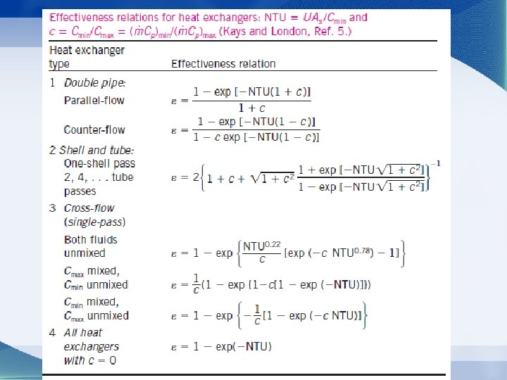
The Effectiveness–NTU Method Effectiveness relations of the heat exchangers typically involve the dimensionless group UAs /Cmin. This quantity is called the number of transfer units NTU. For specified values of U and Cmin, the value of NTU is a measure of the surface area As. Thus, the larger the NTU, the larger the heat exchanger. Capacity ratio The effectiveness of a heat exchanger is a function of the number of transfer units NTU and the capacity ratio c.
Figure 11 -26 Effectiveness for heat exchangers.
Figure 11. 26 -Effectiveness for heat exchangers.
The Effectiveness–NTU Method Table 11 -5 • When all the inlet and outlet temperatures are specified, the size of the heat exchanger can easily be determined using the LMTD method. Alternatively, it can be determined from the effectiveness–NTU method by first evaluating the effectiveness ε from its definition and then the NTU from the appropriate NTU relation.
The Effectiveness–NTU Method
Example 4 -The Effectiveness-NTU Method Repeat Example 2, which was solved with the LMTD method, using the effectiveness–NTU method. A counter-flow double-pipe heat exchanger is to heat water from 20°C to 80°C at a rate of 1. 2 kg/s. The heating is to be accomplished by geothermal water available at 160°C at a mass flow rate of 2 kg/s. The inner tube is thin-walled and has a diameter of 1. 5 cm. If the overall heat transfer coefficient of the heat exchanger is 640 W/m 2. K, determine the length of the heat exchanger required to achieve the desired heating.
Solution •
Solution • That is, the maximum possible heat transfer rate in this heat exchanger is 702. 8 k. W. The actual rate of heat transfer in the heat exchanger is • Thus, the effectiveness of the heat exchanger is • Knowing the effectiveness, the NTU of this counter-flow heat exchanger can be determined from Figure 11– 26 b or the appropriate relation from Table 11– 5. We choose the latter approach for greater accuracy
Solution • Then the heat transfer surface area becomes • To provide this much heat transfer surface area, the length of the tube must be •
The Effectiveness-NTU Method Observations from the effectiveness relations and charts • The value of the effectiveness ranges from 0 to 1. It increases rapidly with NTU for small values (up to about NTU = 1. 5) but rather slowly for larger values. Therefore, the use of a heat exchanger with a large NTU (usually larger than 3) and thus a large size cannot be justified economically, since a large increase in NTU in this case corresponds to a small increase in effectiveness. • For a given NTU and capacity ratio c = Cmin /Cmax, the counter-flow heat exchanger has the highest effectiveness, followed closely by the crossflow heat exchangers with both fluids unmixed. The lowest effectiveness values are encountered in parallel-flow heat exchangers. • The effectiveness of a heat exchanger is independent of the capacity ratio c for NTU values of less than about 0. 3. • The value of the capacity ratio c ranges between 0 and 1. For a given NTU, the effectiveness becomes a maximum for c = 0 (e. g. , boiler, condenser) and a minimum for c = 1 (when the heat capacity rates of the two fluids are equal).
Selection of Heat Exchangers The uncertainty in the predicted value of U can exceed 30 percent. Thus, it is natural to tend to overdesign the heat exchangers. Heat transfer enhancement in heat exchangers is usually accompanied by increased pressure drop, and thus higher pumping power. Therefore, any gain from the enhancement in heat transfer should be weighed against the cost of the accompanying pressure drop. Usually, the more viscous fluid is more suitable for the shell side (larger passage area and thus lower pressure drop) and the fluid with the higher pressure for the tube side. The proper selection of a heat exchanger The rate of heat transfer in the prospective heat exchanger is depends on several factors: • Heat transfer rate • Cost Annual cost of electricity associated with the • Pumping power operation of the pumps and fans: • Size and weight • Type • Materials
Summary • Types of Heat Exchangers • The Overall Heat Transfer Coefficient – Fouling Factor • Analysis of Heat Exchangers • The Log Mean Temperature Difference Method – Counter-Flow Heat Exchangers – Multipass and Cross-Flow Heat Exchangers: Use of a Correction Factor • The Effectiveness-NTU Method • Selection of Heat Exchangers