Heat Exchangers 1 Heat Exchangers A heat exchanger


")


 1 shell pass and 1 tube")


 is referred to as")
 Rating • Checkingthe existing design for compatibility with the")


 Heat Exchangers Evaporator/boiler:")


 effects • Fins reduce the resistance to convection heat transfer, by")


- Slides: 54
Heat Exchangers 1
Heat Exchangers • A heat exchanger is used to exchange heat between two fluids of different temperatures, which are separated by a solid wall. • Heat exchangers are used to carry out energy conversion and utilization. They utlize a wide range of flow configurations. • Applications in heating and air conditioning, power production, waste heat recovery, chemical processing, food processing, sterilization in bio-processes. • Heat exchangers are classified according to flow arrangement and type of construction. Heat Exchangers 2
Heat Exchangers 3
. Flow in a double-pipe heat exchanger.
Heat Exchangers Chee 318 5
The RODbaffle heat exchanger design (Phillips Petroleum Co. )
Tube Bundles
Tube Pitch
Figure 4. 9 -2. Shell-and-tube heat exchangers: (a) 1 shell pass and 1 tube pass (1 -1 exchanger); (b) 1 shell pass and 2 tube passes (1 -2 exchanger).
Shell-and-Tube Heat Exchangers Baffles are used to establish a cross-flow and to induce turbulent mixing of the shellside fluid, both of which enhance convection. Ø The number of tube and shell passes may be varied One Shell Pass and One Tube Pass One Shell Pass, Two Tube Passes Heat Exchangers Two Shell Passes, Four Tube Passes 10
Heat Exchangers Chee 318 11
Heat Exchangers 12
TEMA AES Exchanger
TEMA Designations
Heat Exchangers Chee 318 15
Heat Exchangers Chee 318 16
Heat Exchangers Chee 318 17
Cross-Flow Heat Exchangers Finned-Both Fluids Unmixed Heat Exchangers Unfinned-One Fluid Mixed the Other Unmixed 18
Compact Heat Exchangers • • Widely used to achieve large heat rates per unit volume, particularly when one or both fluids is a gas. Characterized by large heat transfer surface areas per unit volume (>700 m 2/m 3), small flow passages, and laminar flow. Heat Exchangers 19
Heat Exchangers Chee 318 20
Heat Exchangers Chee 318 21
Baffles How do baffles help? Where are they installed and which fluid is directly affected? Common practice is to cut away a segment having a height equal to one-fourth the inside diameter of the shell. Such baffles are called 25 percent baffles.
Baffle Arrangement
Tube sizes Tubes Standard tube lengths are 8, 12, 16 and 20 ft. Tubes are drawn to definite wall thickness in terms of BWG and true outside diameter (OD), and they are available in all common metals.
Tube Pitch The spacing between the tubes (center to center) is referred to as the tube pitch (PT). Triangular or square pitch arrangements are used. Unless the shell side tends to foul badly, triangular pitch is Used.
• Heat Exchanger (HEX) Rating • Checkingthe existing design for compatibility with the user requirements (outlet temperature, heat load etc. ) • given: flow rates, inlet temperatures, allowable pressure drop; thus HT area and passage dimensions • find: heat transfer rate, fluid outlet temperatures, actual pressure drop • HEX Sizing • Thermal and pressure drop considerations, maintenance scheduling with fouling consideration. • given: inlet and outlet temperatures, flow rates, pressure drop • find: dimensions -type and size of HEX Heat Exchangers 26
Assumptions for Basic Design Equations for Sizing • • • steady-state, steady flow • no heat generation in the HEX negligible ΔPE, ΔKE adiabatic processes no phase change (later) constant specific heats and other physical properties. Heat Exchangers 27
Heat Exchanger Analysis LMTD Method • Expression for convection heat transfer for flow of a fluid inside a tube: • For case 3 involving constant surrounding fluid temperature: Heat Exchangers 28
Heat Exchanger Analysis In a two-fluid heat exchanger, consider the hot and cold fluids separately: (11. 1) and (11. 2) v Need to define U and DTlm Heat Exchangers 29
Concentric Tube Construction • Heat Exchangers - : 30
Heat Exchangers 31
Heat Exchangers 32
Heat Exchangers 33
Heat Exchangers 34
Heat Exchangers 35
Heat Exchangers 36
Special Operating Conditions Condenser: Hot fluid is condensing vapor (eg. steam) Heat Exchangers Evaporator/boiler: Cold fluid is evaporating liquid 37
Heat Exchangers
Heat Exchangers 39
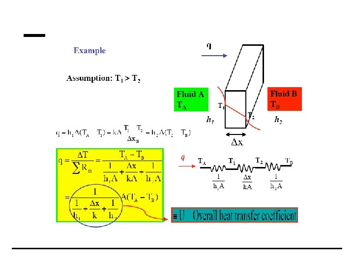
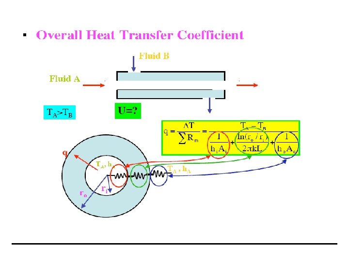
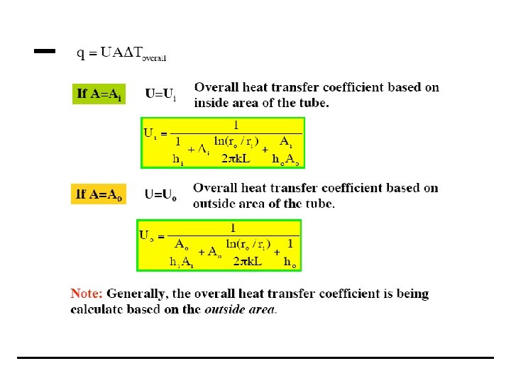
Overall Heat Transfer Coefficient • For tubular heat exchangers we must take into account the conduction resistance in the wall and convection resistances of the fluids at the inner and outer tube surfaces. (11. 3 a) Note that: where inner tube surface outer tube surface Heat Exchangers 43
Heat Exchangers
Fouling • Heat exchanger surfaces are subject to fouling by fluid impurities, rust formation, or other reactions between the fluid and the wall material. The subsequent deposition of a film or scale on the surface can greatly increase the resistance to heat transfer between the fluids. • An additional thermal resistance, can be introduced: The Fouling factor, Rf. Ø Depends on operating temperature, fluid velocity and length of service of heat exchanger. It is variable during heat exchanger operation. Ø Typical values see Heat Transfer for Kern. • The overall heat transfer coefficient can be written: (11. 3 b) Heat Exchangers 45
Heat Exchangers
Heat Exchangers
Fin (extended surface) effects • Fins reduce the resistance to convection heat transfer, by increasing surface area. • Expression for overall heat transfer coefficient includes overall surface efficiency, or temperature effectiveness, ho, of the finned surface, which depends on the type of fin (see also Ch. 3. 6. 4) (11. 3 c) where c is for cold and h for hot fluids respectively Heat Exchangers 48
Example 1 Heat Exchangers
Heat Exchangers
Heat Exchangers
Example 2 Heat Exchangers
Heat Exchangers
Heat Exchangers