P 12022 LVAD POWER TRANSMISSION TEST RIG Erin


- Slides: 18

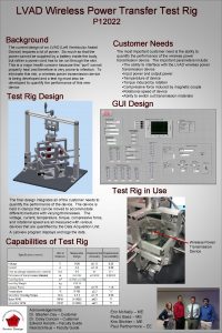
P 12022: LVAD POWER TRANSMISSION TEST RIG Erin Mc. Nally Pedro Baez Paul Parthemore Kris Stichter

TABLE OF CONTENTS Project Background Customer Needs Engineering Specs Needs vs. Specs System Architecture System Concepts System Integration Functional Decomposition Concept Creation Concept Selection Risk Assessment Work Breakdown Project Schedule

BACKGROUND INFORMATION About 5 million Americans are currently living with congestive heart failure (CHF) Heart failure contributes to about 287, 000 deaths per year Current left ventricular assist devices (LVAD) require a cable connecting to the control unit through a hole in the abdomen A permanent opening through the epidermis is highly vulnerable to infection Current wireless power transmission utilizes induction which tends to cause tissue damage due to excessive heat generation SOLUTION: Transmit power wirelessly through the use of a magnetic coupler Test Rig Scope: Design and build functional test rig to analyze performance of current and future wireless power transmission devices

CUSTOMER NEEDS

ENGINEERING SPECS

NEEDS AND SPECS RELATION CHART

SYSTEM ARCHITECTURE

SYSTEM CONCEPTS

SYSTEM INTEGRATION WITH DEVICE TEAM 12022 Responsibilities Measure internal and external temp Measure input and output power 12026 Responsibilities Provide access points to measure motor input and generator output power Measure generator housing torque Measure power, temp, and torque during device ramp up, steady-state operation, and ramp down Incorporate thermistors inside motor and generator housings Power device Provide housing dimensions by end of week 7 Vary load on generator output Measure compressive force between motor and generator Provide ranges for power input and output by end of week 7 Collect data and interpret for entire operating range Provide ranges for heat generation of motor and generator by end of week 7 Measure motor and generator rpm Provide ranges for compressive force vs. separation distance between motor and generator by end of week 7 Provide access point to measure rpm

FUNCTIONAL DECOMPOSITION

CONCEPT CREATION

CONCEPT SCREENING MATRIX – COMPRESSIVE FORCE MEASUREMENTS

CONCEPT SCREENING MATRIX – HEAT MEASUREMENTS

CONCEPT SCREENING MATRIX – HOUSING TORQUE MEASUREMENTS

RISK ASSESSMENT

WORK BREAKDOWN Erin – Team Leader � � � Paul – Integration Engineer � � � Determine power layout for rig Manage integration and communication with 12026 Responsible for electrical aspects of test rig Kris – Design Engineer � � � Manage and update schedule as needed Manage budget and budget concerns Run meetings and keep team members on track Assist with detailed design of test rig Assist with communication with 12026 Manage component drawings and models Responsible for mechanical aspects of test rig Manage research and pricing of components Pedro – Design Engineer Manage customer needs and specs and communication with customer � Manage Edge and documentation revisions � Take meeting notes and minutes � Assist with detailed design of test rig �

PROJECT SCHEDULE

 2020 12022
 Solar power satellites and microwave power transmission
 Hydraulic test rig
 Test rig
 Draw the power triangle
 Air ionization in wireless power transmission
 Wireless power transmission project report doc
 Pneumatic power transmission
 Dispersive power of grating increases with
 1910 machine guarding
 Wireless electricity
 Rig vir jou mylpale op
 Rotary drilling rig components
 Combination reaction
 Leo ger example
 Oil rig oxidation
 Half equations
 Oil rig oxidation
 Rotary system drilling


