Micro transductors 08 Introduction to HSpice Dr Ing
- Slides: 41
Micro transductors ’ 08 Introduction to HSpice Dr. -Ing. Frank Sill Department of Electrical Engineering, Federal University of Minas Gerais, Av. Antônio Carlos 6627, CEP: 31270 -010, Belo Horizonte (MG), Brazil franksill@ufmg. br http: //www. cpdee. ufmg. br/~frank/
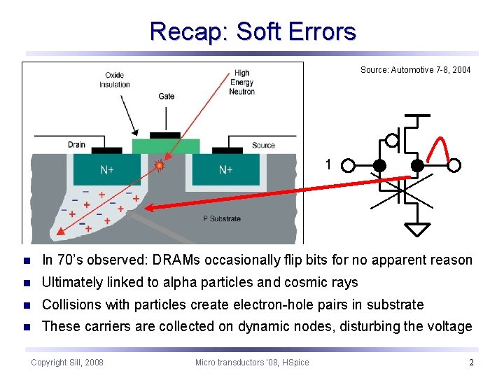
Recap: Soft Errors Source: Automotive 7 -8, 2004 1 n In 70’s observed: DRAMs occasionally flip bits for no apparent reason n Ultimately linked to alpha particles and cosmic rays n Collisions with particles create electron-hole pairs in substrate n These carriers are collected on dynamic nodes, disturbing the voltage Copyright Sill, 2008 Micro transductors ‘ 08, HSpice 2
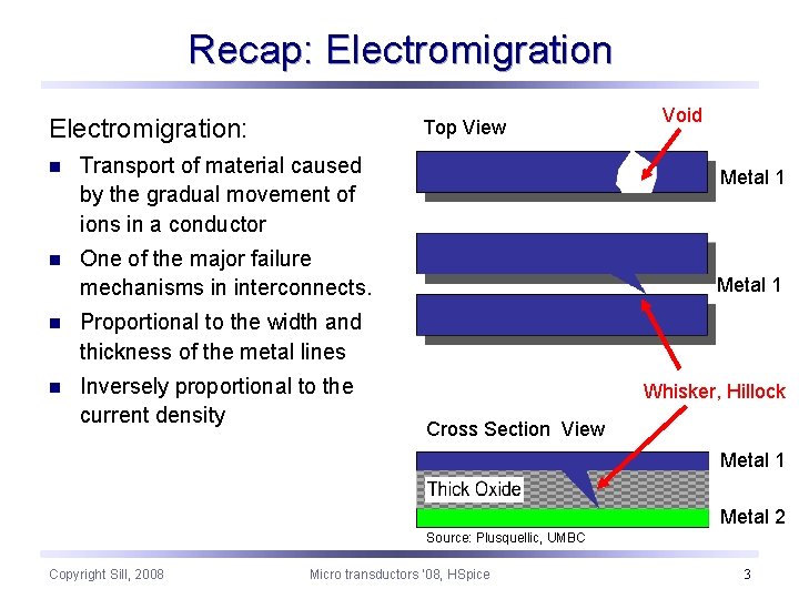
Recap: Electromigration: Top View n Transport of material caused by the gradual movement of ions in a conductor n One of the major failure mechanisms in interconnects. n Proportional to the width and thickness of the metal lines n Inversely proportional to the current density Void Metal 1 Whisker, Hillock Cross Section View Metal 1 Metal 2 Source: Plusquellic, UMBC Copyright Sill, 2008 Micro transductors ‘ 08, HSpice 3
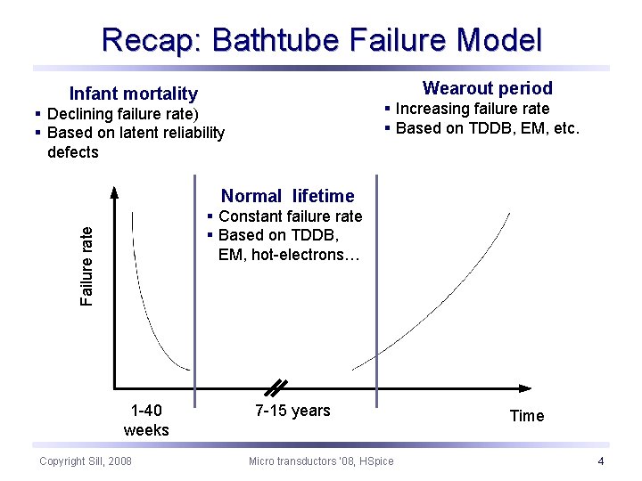
Recap: Bathtube Failure Model Wearout period Infant mortality § Increasing failure rate § Based on TDDB, EM, etc. § Declining failure rate) § Based on latent reliability defects Normal lifetime Failure rate § Constant failure rate § Based on TDDB, EM, hot-electrons… 1 -40 weeks Copyright Sill, 2008 7 -15 years Micro transductors ‘ 08, HSpice Time 4
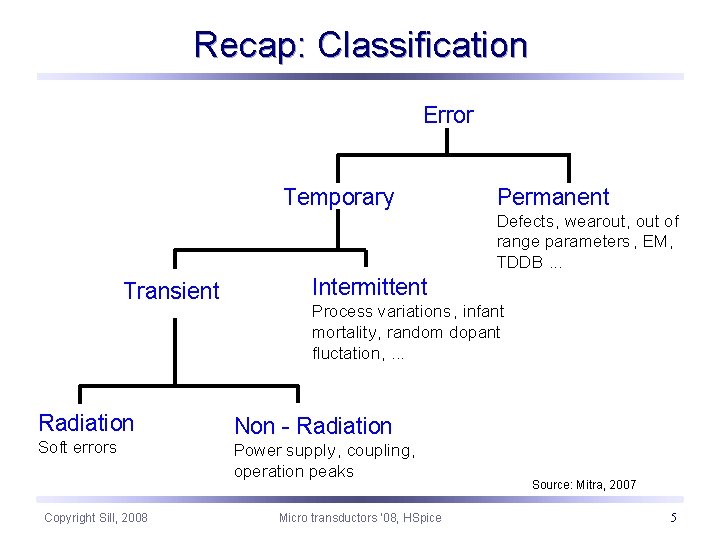
Recap: Classification Error Temporary Permanent Defects, wearout, out of range parameters , EM, TDDB. . . Transient Radiation Soft errors Copyright Sill, 2008 Intermittent Process variations , infant mortality, random dopant fluctation, . . . Non - Radiation Power supply, coupling, operation peaks Micro transductors ‘ 08, HSpice Source: Mitra, 2007 5
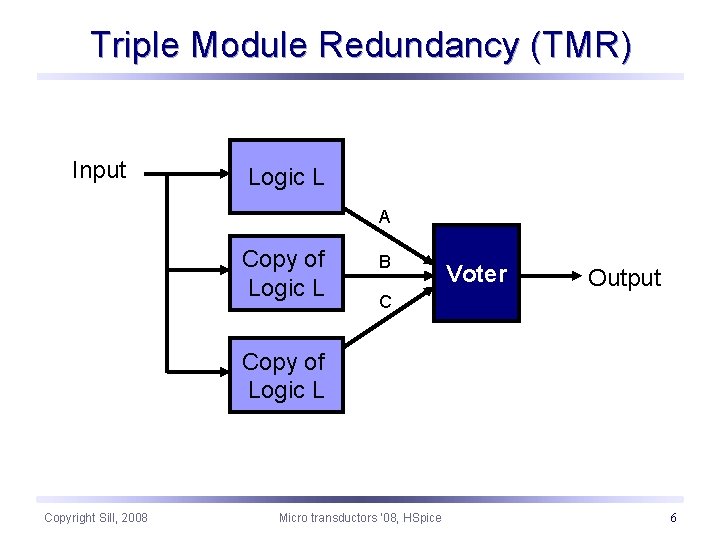
Triple Module Redundancy (TMR) Input Logic L A Copy of Logic L B Voter Output C Copy of Logic L Copyright Sill, 2008 Micro transductors ‘ 08, HSpice 6
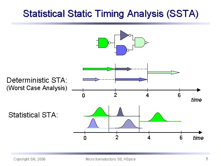
Statistical Static Timing Analysis (SSTA) Deterministic STA: (Worst Case Analysis) 0 2 4 6 time Statistical STA: Copyright Sill, 2008 Micro transductors ‘ 08, HSpice time 7
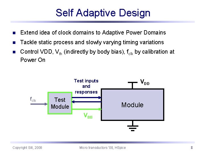
Self Adaptive Design n Extend idea of clock domains to Adaptive Power Domains n Tackle static process and slowly varying timing variations n Control VDD, Vth (indirectly by body bias), fclk by calibration at Power On Test inputs and responses fclk Test Module VDD Module VBB Copyright Sill, 2008 Micro transductors ‘ 08, HSpice 8
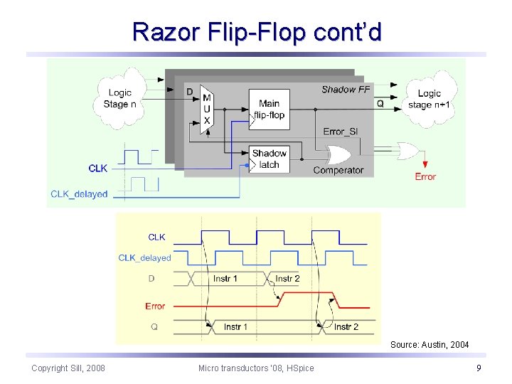
Razor Flip-Flop cont’d Source: Austin, 2004 Copyright Sill, 2008 Micro transductors ‘ 08, HSpice 9
What is Spice? n Simulation Program with Integrated Circuit Emphasis n General purpose analog circuit simulator n Used in IC and board-level design for check of integrity of circuit designs and prediction of circuit behavior n Developed at Electronics Research Laboratory of the University of California, Berkeley n SPICE simulation is industry-standard for verification of circuit operation at transistor level before manufacturing n Description of circuit elements (transistors, resistors, capacitors, etc. ) and connections by netlists n Netlists translated into nonlinear differential algebraic equations n Solving by implicit integration methods, Newton's method and sparse matrix techniques Copyright Sill, 2008 Micro transductors ‘ 08, HSpice Sill, HSpice 10
HSpice features n Superior convergence n Accurate modeling, including many foundry models n Hierarchical node naming and reference n Circuit optimization for models and cells, with incremental or simultaneous Multiparameter optimizations in AC, DC, and transient simulations n Monte Carlo and worst-case design support n Input, output, and behavioral algebraics for cells with parameters n Cell characterization tools to characterize standard cell libraries n Geometric lossy-coupled transmission lines for PCB, multi-chip, package, and IC technologies Copyright Sill, 2008 Micro transductors ‘ 08, HSpice 11
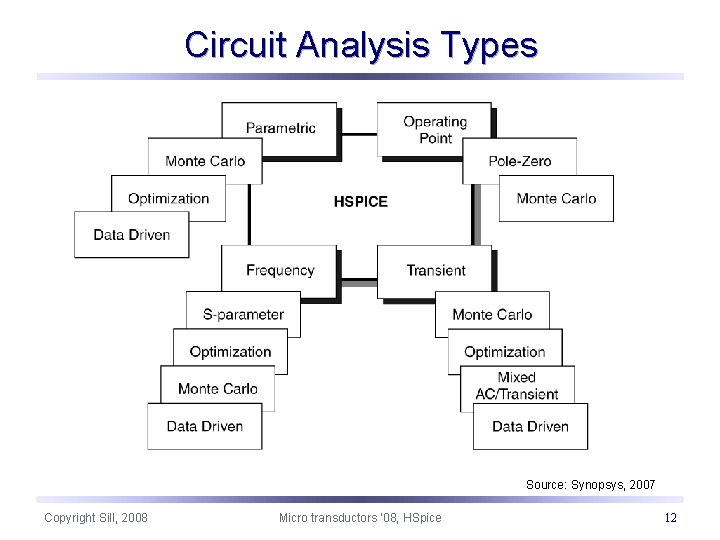
Circuit Analysis Types Source: Synopsys, 2007 Copyright Sill, 2008 Micro transductors ‘ 08, HSpice 12
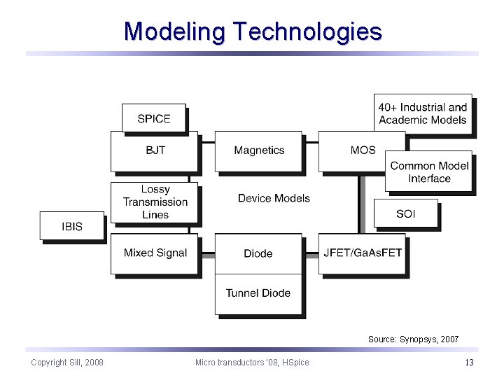
Modeling Technologies Source: Synopsys, 2007 Copyright Sill, 2008 Micro transductors ‘ 08, HSpice 13
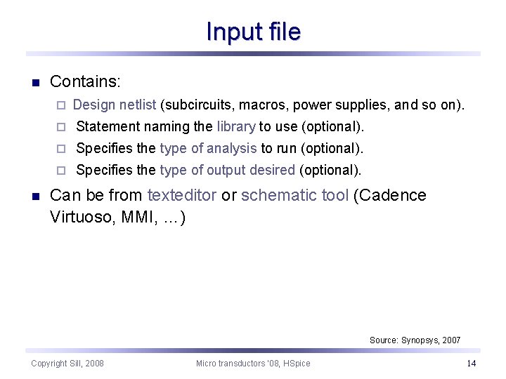
Input file n Contains: ¨ n Design netlist (subcircuits, macros, power supplies, and so on). ¨ Statement naming the library to use (optional). ¨ Specifies the type of analysis to run (optional). ¨ Specifies the type of output desired (optional). Can be from texteditor or schematic tool (Cadence Virtuoso, MMI, …) Source: Synopsys, 2007 Copyright Sill, 2008 Micro transductors ‘ 08, HSpice 14
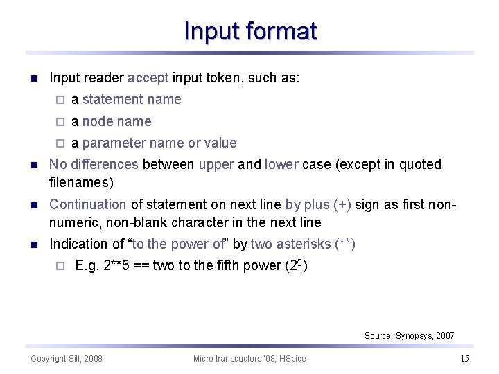
Input format n Input reader accept input token, such as: ¨ a statement name ¨ a node name ¨ a parameter name or value n No differences between upper and lower case (except in quoted filenames) n Continuation of statement on next line by plus (+) sign as first nonnumeric, non-blank character in the next line n Indication of “to the power of” by two asterisks (**) ¨ E. g. 2**5 == two to the fifth power (25) Source: Synopsys, 2007 Copyright Sill, 2008 Micro transductors ‘ 08, HSpice 15
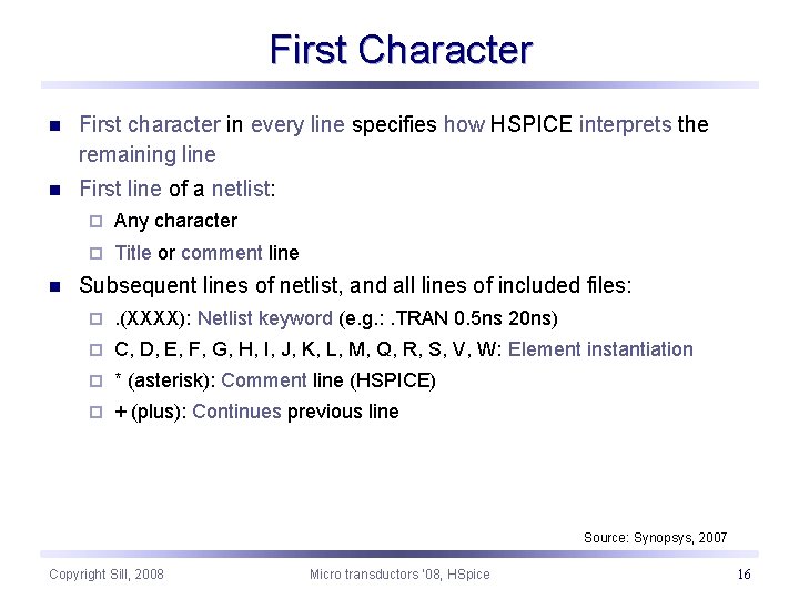
First Character n First character in every line specifies how HSPICE interprets the remaining line n First line of a netlist: n ¨ Any character ¨ Title or comment line Subsequent lines of netlist, and all lines of included files: ¨ . (XXXX): Netlist keyword (e. g. : . TRAN 0. 5 ns 20 ns) ¨ C, D, E, F, G, H, I, J, K, L, M, Q, R, S, V, W: Element instantiation ¨ * (asterisk): Comment line (HSPICE) ¨ + (plus): Continues previous line Source: Synopsys, 2007 Copyright Sill, 2008 Micro transductors ‘ 08, HSpice 16
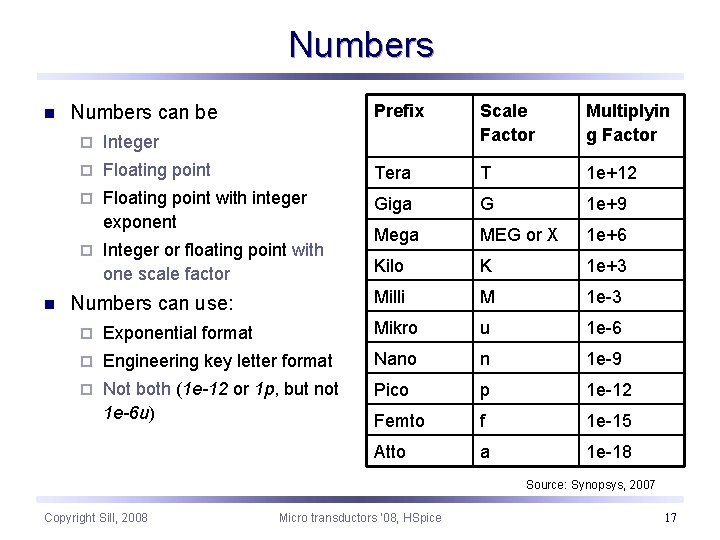
Numbers n n Numbers can be Prefix Scale Factor Multiplyin g Factor ¨ Integer ¨ Floating point Tera T 1 e+12 ¨ Floating point with integer exponent Giga G 1 e+9 ¨ Integer or floating point with one scale factor Mega MEG or X 1 e+6 Kilo K 1 e+3 Milli M 1 e-3 Numbers can use: ¨ Exponential format Mikro u 1 e-6 ¨ Engineering key letter format Nano n 1 e-9 ¨ Not both (1 e-12 or 1 p, but not 1 e-6 u) Pico p 1 e-12 Femto f 1 e-15 Atto a 1 e-18 Source: Synopsys, 2007 Copyright Sill, 2008 Micro transductors ‘ 08, HSpice 17
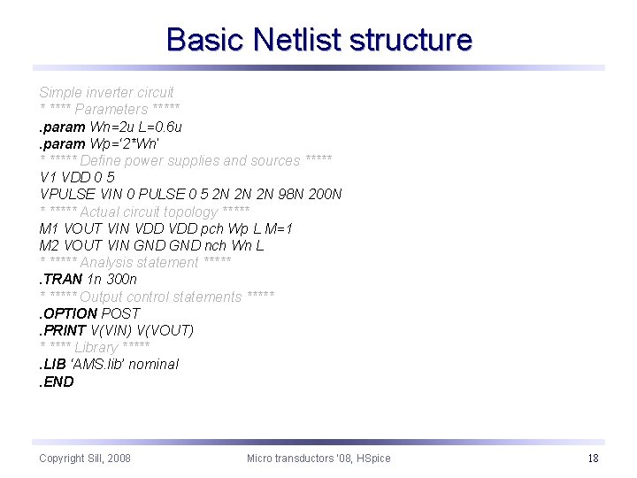
Basic Netlist structure Simple inverter circuit * **** Parameters *****. param Wn=2 u L=0. 6 u. param Wp=‘ 2*Wn’ * ***** Define power supplies and sources ***** V 1 VDD 0 5 VPULSE VIN 0 PULSE 0 5 2 N 2 N 2 N 98 N 200 N * ***** Actual circuit topology ***** M 1 VOUT VIN VDD pch Wp L M=1 M 2 VOUT VIN GND nch Wn L * ***** Analysis statement *****. TRAN 1 n 300 n * ***** Output control statements *****. OPTION POST. PRINT V(VIN) V(VOUT) * **** Library *****. LIB ‘AMS. lib’ nominal. END Copyright Sill, 2008 Micro transductors ‘ 08, HSpice 18
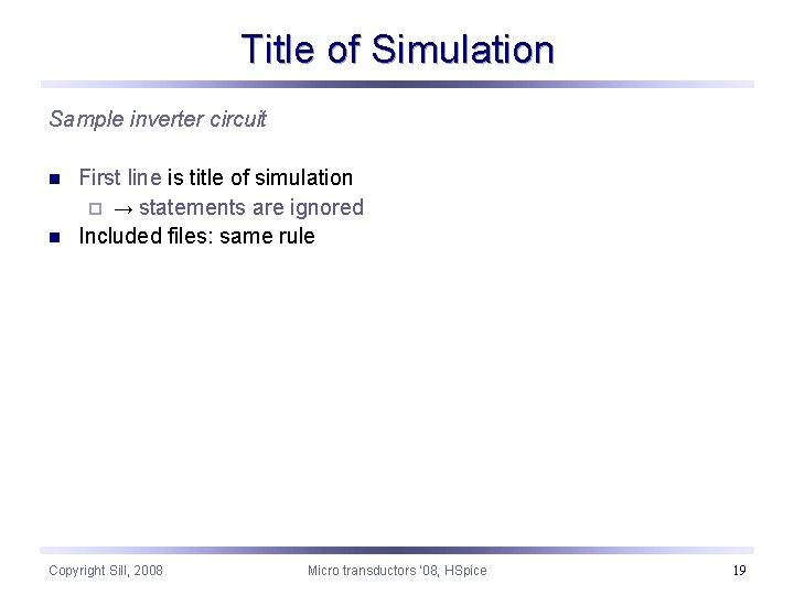
Title of Simulation Sample inverter circuit n n First line is title of simulation ¨ → statements are ignored Included files: same rule Copyright Sill, 2008 Micro transductors ‘ 08, HSpice 19
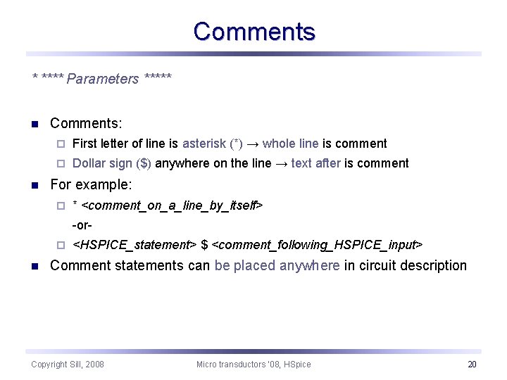
Comments * **** Parameters ***** n n Comments: ¨ First letter of line is asterisk (*) → whole line is comment ¨ Dollar sign ($) anywhere on the line → text after is comment For example: ¨ * <comment_on_a_line_by_itself> -or- ¨ n <HSPICE_statement> $ <comment_following_HSPICE_input> Comment statements can be placed anywhere in circuit description Copyright Sill, 2008 Micro transductors ‘ 08, HSpice 20
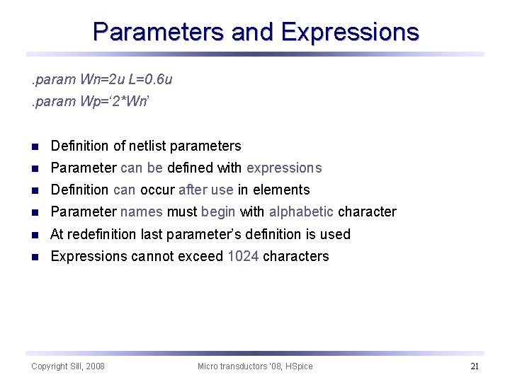
Parameters and Expressions. param Wn=2 u L=0. 6 u. param Wp=‘ 2*Wn’ n Definition of netlist parameters n Parameter can be defined with expressions n Definition can occur after use in elements n Parameter names must begin with alphabetic character n At redefinition last parameter’s definition is used n Expressions cannot exceed 1024 characters Copyright Sill, 2008 Micro transductors ‘ 08, HSpice 21
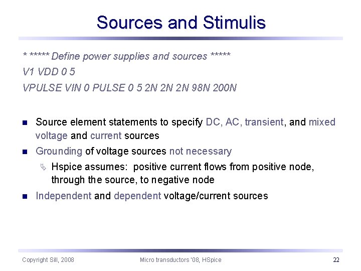
Sources and Stimulis * ***** Define power supplies and sources ***** V 1 VDD 0 5 VPULSE VIN 0 PULSE 0 5 2 N 2 N 2 N 98 N 200 N n Source element statements to specify DC, AC, transient, and mixed voltage and current sources n Grounding of voltage sources not necessary Ä n Hspice assumes: positive current flows from positive node, through the source, to negative node Independent and dependent voltage/current sources Copyright Sill, 2008 Micro transductors ‘ 08, HSpice 22
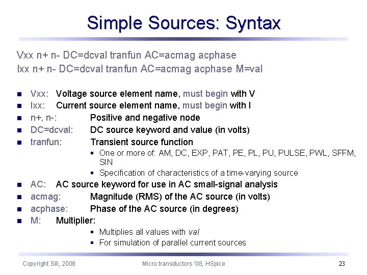
Simple Sources: Syntax Vxx n+ n- DC=dcval tranfun AC=acmag acphase Ixx n+ n- DC=dcval tranfun AC=acmag acphase M=val n n n Vxx: Voltage source element name, must begin with V Ixx: Current source element name, must begin with I n+, n-: Positive and negative node DC=dcval: DC source keyword and value (in volts) tranfun: Transient source function § One or more of: AM, DC, EXP, PAT, PE, PL, PULSE, PWL, SFFM, SIN § Specification of characteristics of a time-varying source n n AC: AC source keyword for use in AC small-signal analysis acmag: Magnitude (RMS) of the AC source (in volts) acphase: Phase of the AC source (in degrees) M: Multiplier: § Multiplies all values with val § For simulation of parallel current sources Copyright Sill, 2008 Micro transductors ‘ 08, HSpice 23
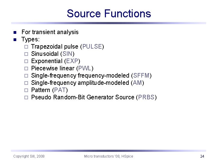
Source Functions n n For transient analysis Types: ¨ Trapezoidal pulse (PULSE) ¨ Sinusoidal (SIN) ¨ Exponential (EXP) ¨ Piecewise linear (PWL) ¨ Single-frequency-modeled (SFFM) ¨ Single-frequency amplitude-modeled (AM) ¨ Pattern (PAT) ¨ Pseudo Random-Bit Generator Source (PRBS) Copyright Sill, 2008 Micro transductors ‘ 08, HSpice 24
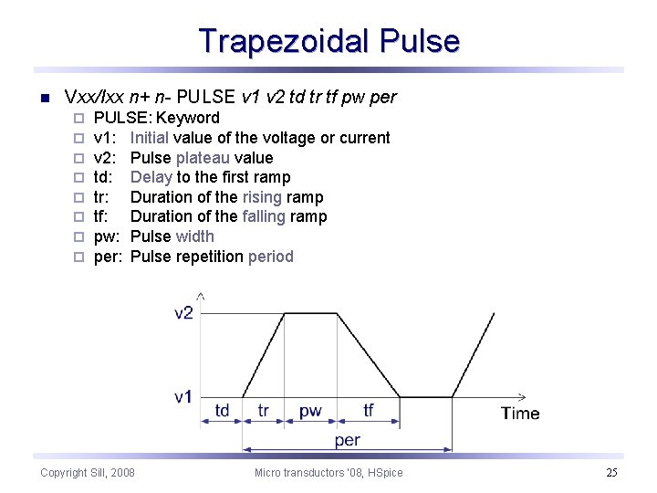
Trapezoidal Pulse n Vxx/Ixx n+ n- PULSE v 1 v 2 td tr tf pw per ¨ ¨ ¨ ¨ PULSE: Keyword v 1: Initial value of the voltage or current v 2: Pulse plateau value td: Delay to the first ramp tr: Duration of the rising ramp tf: Duration of the falling ramp pw: Pulse width per: Pulse repetition period Copyright Sill, 2008 Micro transductors ‘ 08, HSpice 25
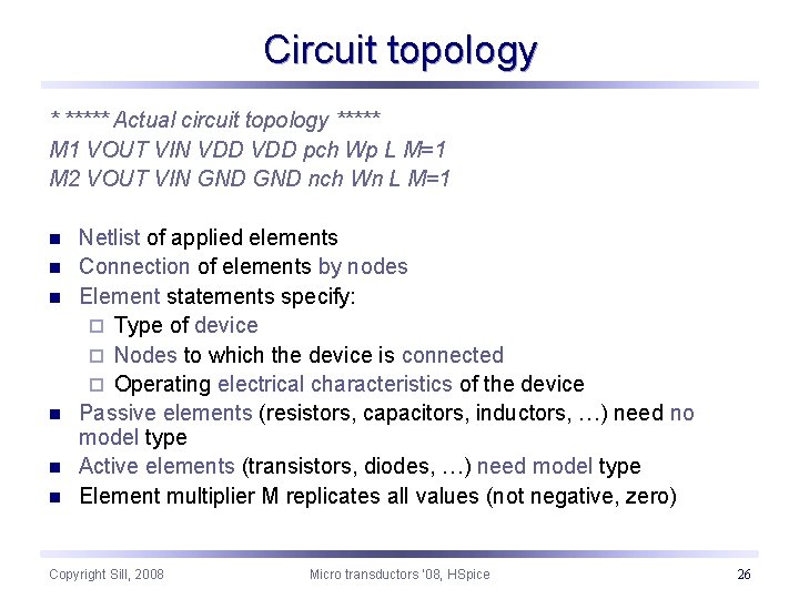
Circuit topology * ***** Actual circuit topology ***** M 1 VOUT VIN VDD pch Wp L M=1 M 2 VOUT VIN GND nch Wn L M=1 n n n Netlist of applied elements Connection of elements by nodes Element statements specify: ¨ Type of device ¨ Nodes to which the device is connected ¨ Operating electrical characteristics of the device Passive elements (resistors, capacitors, inductors, …) need no model type Active elements (transistors, diodes, …) need model type Element multiplier M replicates all values (not negative, zero) Copyright Sill, 2008 Micro transductors ‘ 08, HSpice 26
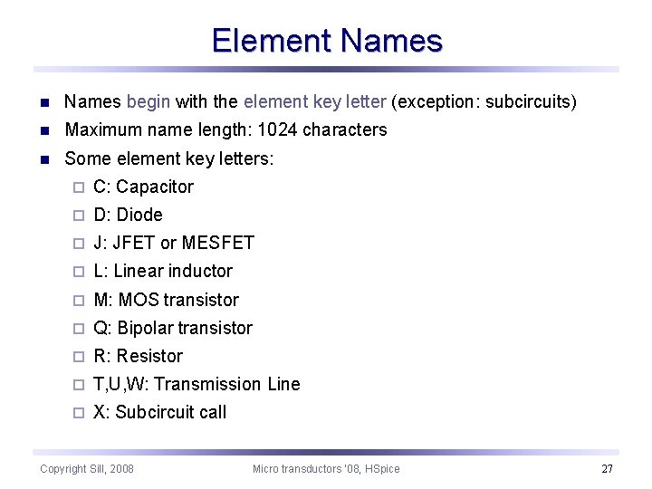
Element Names n Names begin with the element key letter (exception: subcircuits) n Maximum name length: 1024 characters n Some element key letters: ¨ C: Capacitor ¨ D: Diode ¨ J: JFET or MESFET ¨ L: Linear inductor ¨ M: MOS transistor ¨ Q: Bipolar transistor ¨ R: Resistor ¨ T, U, W: Transmission Line ¨ X: Subcircuit call Copyright Sill, 2008 Micro transductors ‘ 08, HSpice 27
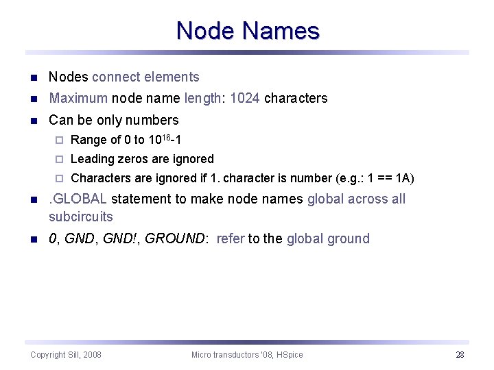
Node Names n Nodes connect elements n Maximum node name length: 1024 characters n Can be only numbers ¨ Range of 0 to 1016 -1 ¨ Leading zeros are ignored ¨ Characters are ignored if 1. character is number (e. g. : 1 == 1 A) n . GLOBAL statement to make node names global across all subcircuits n 0, GND!, GROUND: refer to the global ground Copyright Sill, 2008 Micro transductors ‘ 08, HSpice 28
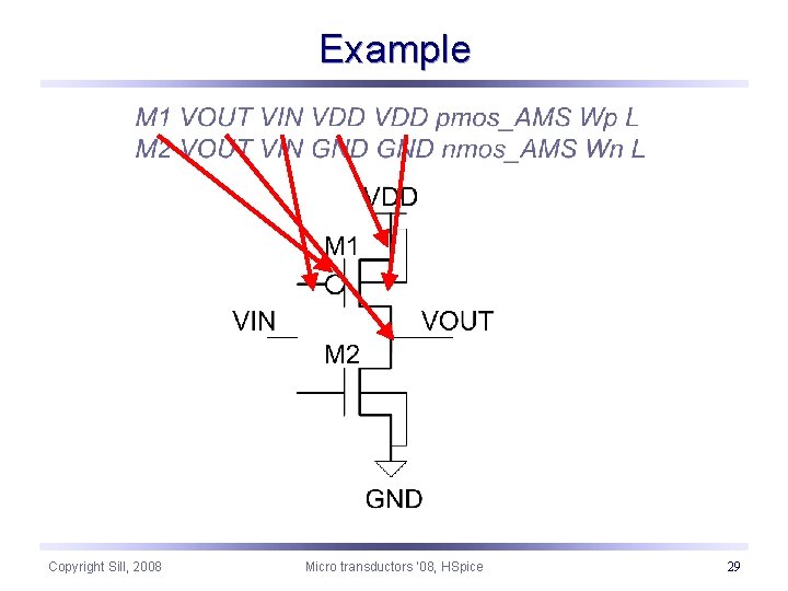
Example Copyright Sill, 2008 Micro transductors ‘ 08, HSpice 29
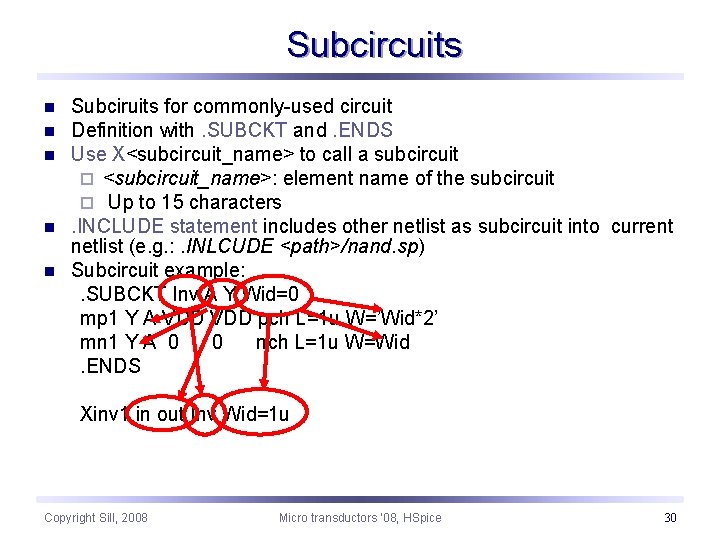
Subcircuits n n n Subciruits for commonly-used circuit Definition with. SUBCKT and. ENDS Use X<subcircuit_name> to call a subcircuit ¨ <subcircuit_name>: element name of the subcircuit ¨ Up to 15 characters. INCLUDE statement includes other netlist as subcircuit into current netlist (e. g. : . INLCUDE <path>/nand. sp) Subcircuit example: . SUBCKT Inv A Y Wid=0 mp 1 Y A VDD pch L=1 u W=’Wid*2’ mn 1 Y A 0 0 nch L=1 u W=Wid. ENDS Xinv 1 in out Inv Wid=1 u Copyright Sill, 2008 Micro transductors ‘ 08, HSpice 30
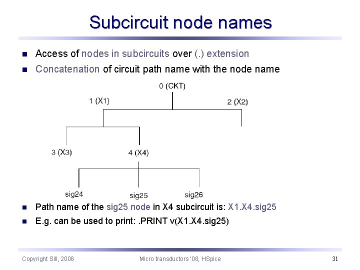
Subcircuit node names n Access of nodes in subcircuits over (. ) extension n Concatenation of circuit path name with the node name n Path name of the sig 25 node in X 4 subcircuit is: X 1. X 4. sig 25 n E. g. can be used to print: . PRINT v(X 1. X 4. sig 25) Copyright Sill, 2008 Micro transductors ‘ 08, HSpice 31
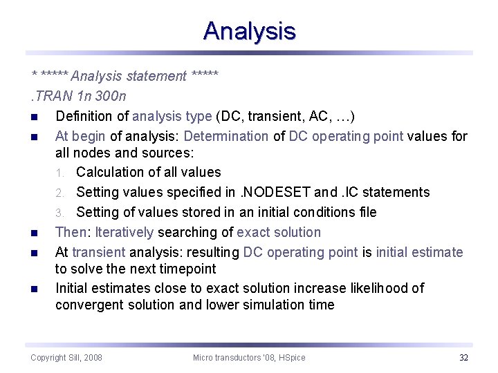
Analysis * ***** Analysis statement *****. TRAN 1 n 300 n n Definition of analysis type (DC, transient, AC, …) n At begin of analysis: Determination of DC operating point values for all nodes and sources: 1. Calculation of all values 2. Setting values specified in. NODESET and. IC statements 3. Setting of values stored in an initial conditions file n Then: Iteratively searching of exact solution n At transient analysis: resulting DC operating point is initial estimate to solve the next timepoint n Initial estimates close to exact solution increase likelihood of convergent solution and lower simulation time Copyright Sill, 2008 Micro transductors ‘ 08, HSpice 32
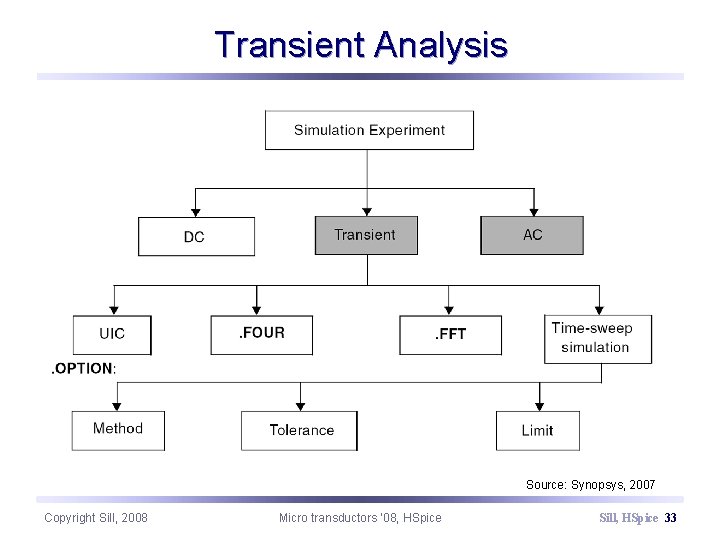
Transient Analysis Source: Synopsys, 2007 Copyright Sill, 2008 Micro transductors ‘ 08, HSpice Sill, HSpice 33
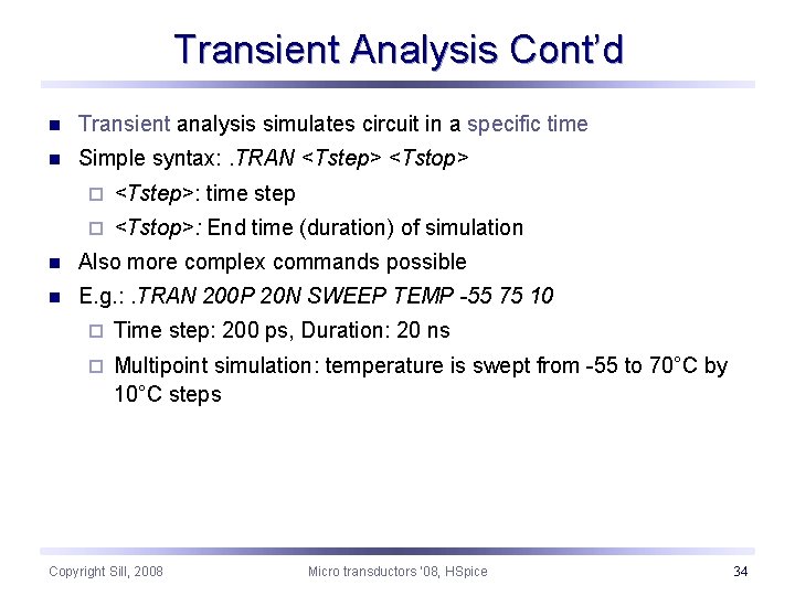
Transient Analysis Cont’d n Transient analysis simulates circuit in a specific time n Simple syntax: . TRAN <Tstep> <Tstop> ¨ <Tstep>: time step ¨ <Tstop>: End time (duration) of simulation n Also more complex commands possible n E. g. : . TRAN 200 P 20 N SWEEP TEMP -55 75 10 ¨ Time step: 200 ps, Duration: 20 ns ¨ Multipoint simulation: temperature is swept from -55 to 70°C by 10°C steps Copyright Sill, 2008 Micro transductors ‘ 08, HSpice 34
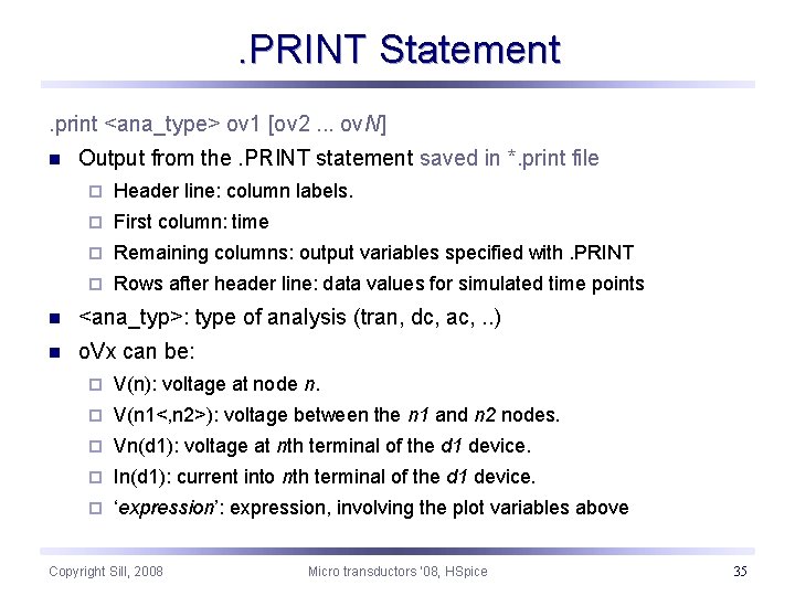
. PRINT Statement. print <ana_type> ov 1 [ov 2. . . ov. N] n Output from the. PRINT statement saved in *. print file ¨ Header line: column labels. ¨ First column: time ¨ Remaining columns: output variables specified with. PRINT ¨ Rows after header line: data values for simulated time points n <ana_typ>: type of analysis (tran, dc, ac, . . ) n o. Vx can be: ¨ V(n): voltage at node n. ¨ V(n 1<, n 2>): voltage between the n 1 and n 2 nodes. ¨ Vn(d 1): voltage at nth terminal of the d 1 device. ¨ In(d 1): current into nth terminal of the d 1 device. ¨ ‘expression’: expression, involving the plot variables above Copyright Sill, 2008 Micro transductors ‘ 08, HSpice 35
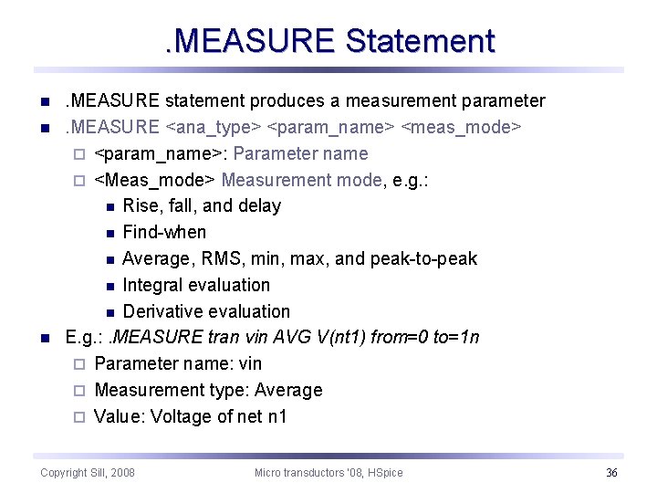
. MEASURE Statement n n n . MEASURE statement produces a measurement parameter. MEASURE <ana_type> <param_name> <meas_mode> ¨ <param_name>: Parameter name ¨ <Meas_mode> Measurement mode, e. g. : n Rise, fall, and delay n Find-when n Average, RMS, min, max, and peak-to-peak n Integral evaluation n Derivative evaluation E. g. : . MEASURE tran vin AVG V(nt 1) from=0 to=1 n ¨ Parameter name: vin ¨ Measurement type: Average ¨ Value: Voltage of net n 1 Copyright Sill, 2008 Micro transductors ‘ 08, HSpice 36
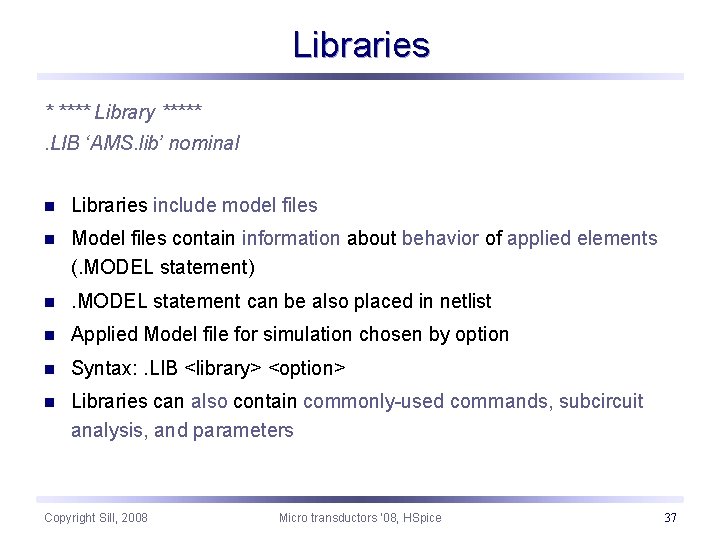
Libraries * **** Library *****. LIB ‘AMS. lib’ nominal n Libraries include model files n Model files contain information about behavior of applied elements (. MODEL statement) n . MODEL statement can be also placed in netlist n Applied Model file for simulation chosen by option n Syntax: . LIB <library> <option> n Libraries can also contain commonly-used commands, subcircuit analysis, and parameters Copyright Sill, 2008 Micro transductors ‘ 08, HSpice 37
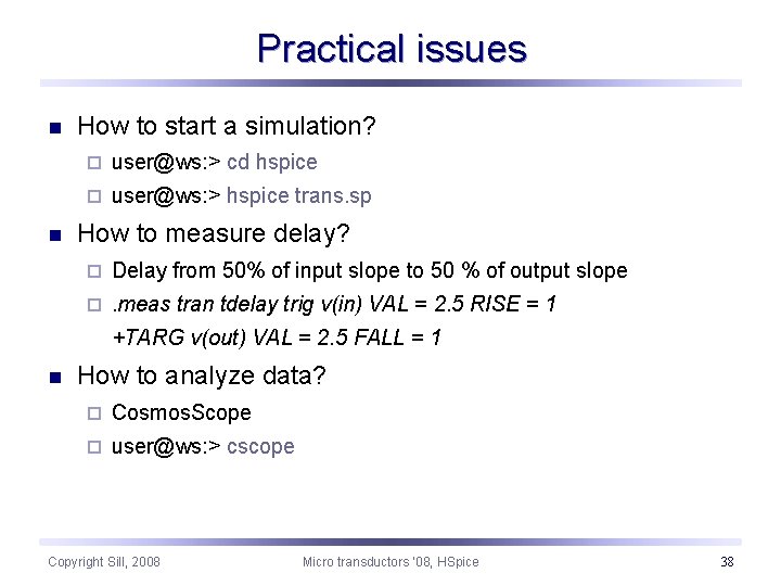
Practical issues n n How to start a simulation? ¨ user@ws: > cd hspice ¨ user@ws: > hspice trans. sp How to measure delay? ¨ Delay from 50% of input slope to 50 % of output slope ¨ . meas tran tdelay trig v(in) VAL = 2. 5 RISE = 1 +TARG v(out) VAL = 2. 5 FALL = 1 n How to analyze data? ¨ Cosmos. Scope ¨ user@ws: > cscope Copyright Sill, 2008 Micro transductors ‘ 08, HSpice 38
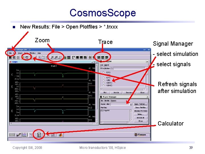
Cosmos. Scope n New Results: File > Open Plotfiles > *. trxxx Zoom Trace Signal Manager - select simulation - select signals Refresh signals after simulation Calculator Copyright Sill, 2008 Micro transductors ‘ 08, HSpice 39
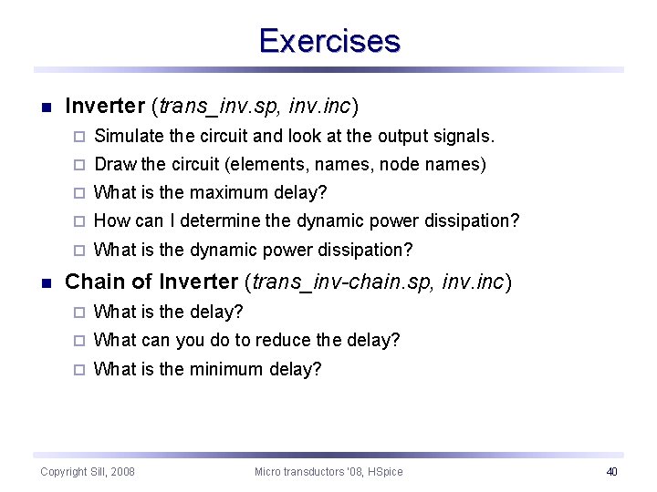
Exercises n n Inverter (trans_inv. sp, inv. inc) ¨ Simulate the circuit and look at the output signals. ¨ Draw the circuit (elements, names, node names) ¨ What is the maximum delay? ¨ How can I determine the dynamic power dissipation? ¨ What is the dynamic power dissipation? Chain of Inverter (trans_inv-chain. sp, inv. inc) ¨ What is the delay? ¨ What can you do to reduce the delay? ¨ What is the minimum delay? Copyright Sill, 2008 Micro transductors ‘ 08, HSpice 40
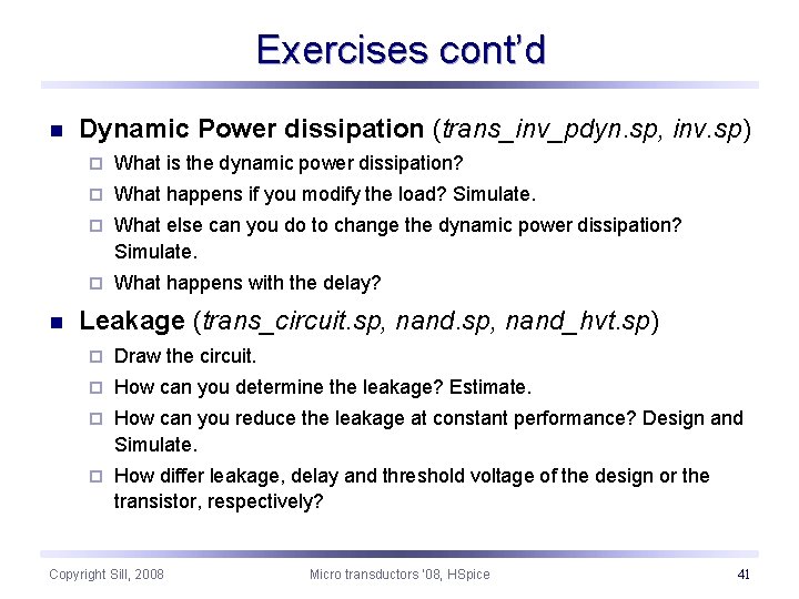
Exercises cont’d n n Dynamic Power dissipation (trans_inv_pdyn. sp, inv. sp) ¨ What is the dynamic power dissipation? ¨ What happens if you modify the load? Simulate. ¨ What else can you do to change the dynamic power dissipation? Simulate. ¨ What happens with the delay? Leakage (trans_circuit. sp, nand_hvt. sp) ¨ Draw the circuit. ¨ How can you determine the leakage? Estimate. ¨ How can you reduce the leakage at constant performance? Design and Simulate. ¨ How differ leakage, delay and threshold voltage of the design or the transistor, respectively? Copyright Sill, 2008 Micro transductors ‘ 08, HSpice 41