Lesson 7 Fuels And Fuel Systems Fuels And



- Slides: 56
Lesson 7: Fuels And Fuel Systems
Fuels And Fuel Systems • Fuel: The energy source for the combustion process • Combustion occurs when fuel comes into contact with oxygen, and the temperature of the mixture is raised to its kindling point. • The fuel and oxygen mix, and oxidation, or burning, occurs.
Air : Fuel Ratio • Stoichiometric is a chemically correct mixture in which all of the chemical elements are used and none are left over. (15: 1) • Fifteen pounds of air to one pound of gasoline. • 15: 1 = 0. 067
Air : Fuel Ratio What air - fuel mixture would be used to produce the most power?
Air : Fuel Ratio • The design of the engine induction system and the valve timing requires a mixture that is slightly richer than chemically perfect in order to produce the maximum power. • This also runs cooler and prevents overheating and detonation under high engine loads. • Maximum power is normally considered to be produced with a mixture of approximately 12: 1 or 0. 083.
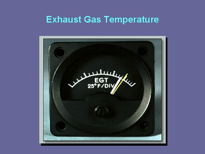
Exhaust Gas Temperature • There is a direct relationship between the temperature of the exhaust gas and the mixture ratio being burned. • As mixture ratio is leaned, the EGT rises until peak temperature is reached, and then it drops off. • This peak EGT will always be reached with the same air : fuel ratio regardless of the power. • Used as a reference for adjusting the mixture.
Exhaust Gas Temperature
Specific Fuel Consumption • The number of pounds of fuel burned per hour for each horsepower developed. Pounds of fuel burned per hour Brake horsepower produced • Used to rate or to compare the performance of aircraft engines. • Used rather than thermal efficiency.
Thermal Efficiency • The ratio of useful work done by an engine to the heat energy of the fuel it uses, expressed in work or heat units.
Reciprocating Engine Fuels
Reciprocating Engine Fuels • Composition • Aviation gasoline is a hydrocarbon fuel refined from crude oil. • Straight-run gasoline • All gasolines are blends of different hydrocarbons and additives. • Annual US usage of avgas was approximately 0. 14% of motor gasoline consumption in 2008.
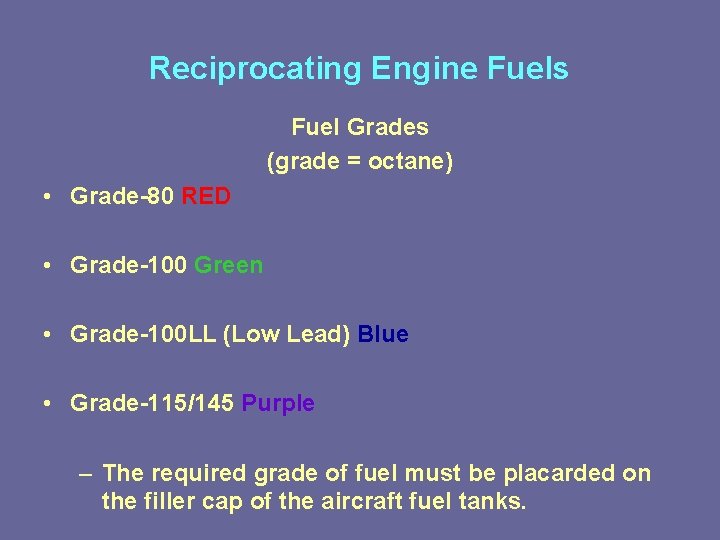
Reciprocating Engine Fuels Fuel Grades (grade = octane) • Grade-80 RED • Grade-100 Green • Grade-100 LL (Low Lead) Blue • Grade-115/145 Purple – The required grade of fuel must be placarded on the filler cap of the aircraft fuel tanks.
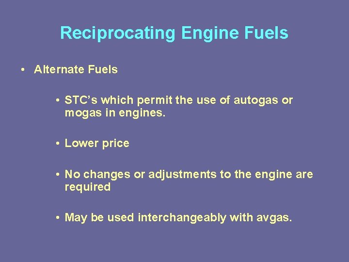
Reciprocating Engine Fuels • Alternate Fuels • STC’s which permit the use of autogas or mogas in engines. • Lower price • No changes or adjustments to the engine are required • May be used interchangeably with avgas.
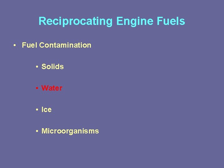
Reciprocating Engine Fuels • Fuel Contamination • Solids • Water • Ice • Microorganisms
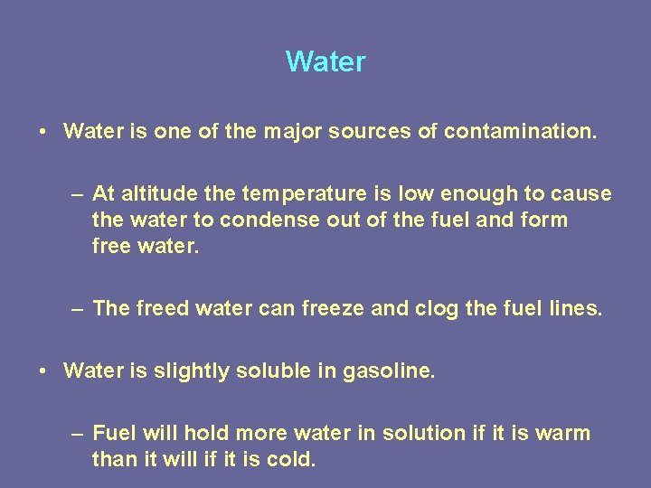
Water • Water is one of the major sources of contamination. – At altitude the temperature is low enough to cause the water to condense out of the fuel and form free water. – The freed water can freeze and clog the fuel lines. • Water is slightly soluble in gasoline. – Fuel will hold more water in solution if it is warm than it will if it is cold.
Fuel Metering Systems
Fuel Metering Systems • Principal Function is to sense the amount of air entering the engine at any moment and meter into that air an amount of fuel that will provide a uniform air : fuel ratio. • System will provide a uniform air : fuel ratio as the airflow varies.
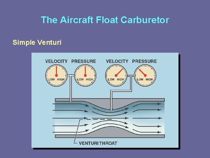
The Aircraft Float Carburetor • Airflow Sensing • The air measuring unit is the venturi. • Makes use of a basic law a physics: As the velocity of a gas or liquid increases, the pressure decreases.
The Aircraft Float Carburetor Simple Venturi
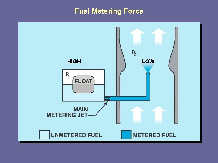
The Aircraft Float Carburetor • Fuel Metering Force • Fuel from the aircraft’s tank is delivered to the float bowl of the carburetor. • The main fuel nozzle is located in the center of the venturi. • When air is flowing in the venturi a pressure differential between the venturi and the float chamber exist (Fuel Metering Force).
Fuel Metering Force HIGH LOW
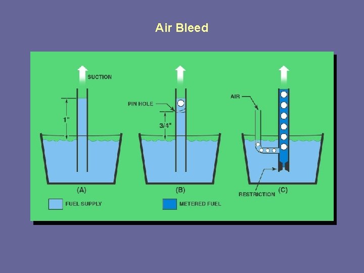
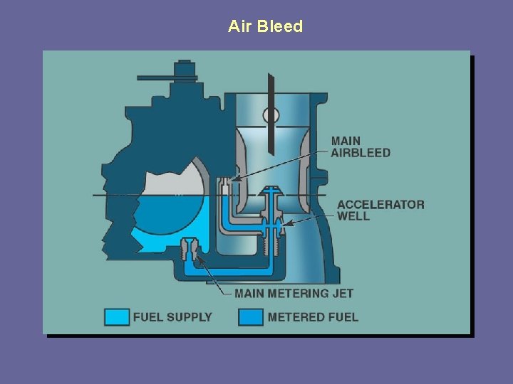
The Aircraft Float Carburetor • Air Bleed • Air bled into the main metering system decreases the fuel density and destroys surface tension. • This results in better vaporization and control of fuel discharge, especially at lower engine speeds.
Air Bleed
Air Bleed
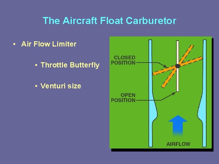
The Aircraft Float Carburetor • Air Flow Limiter • Throttle Butterfly • Venturi size
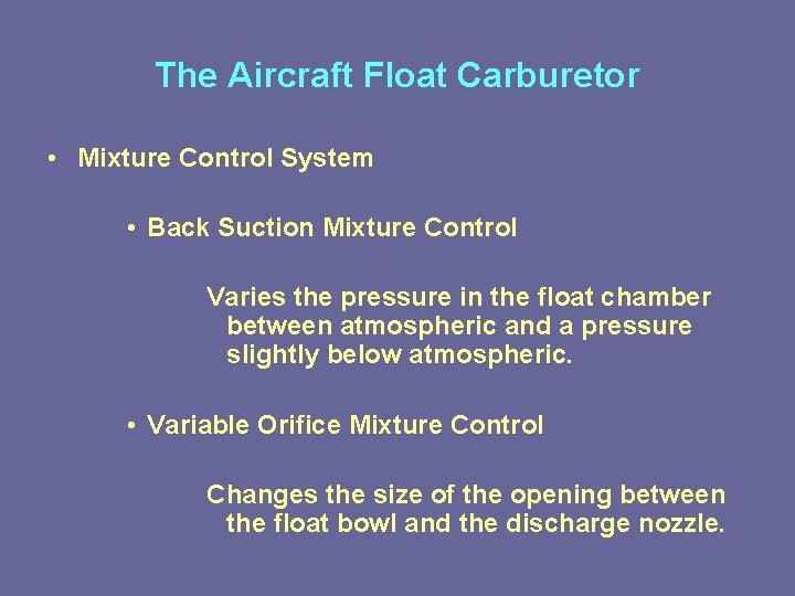
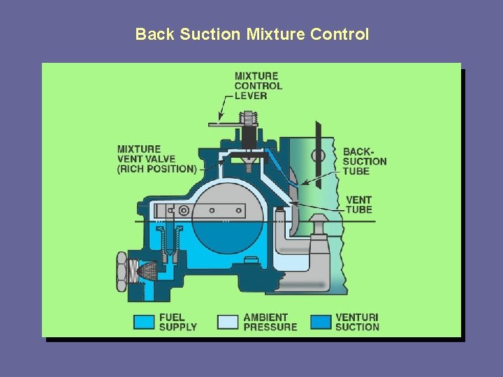
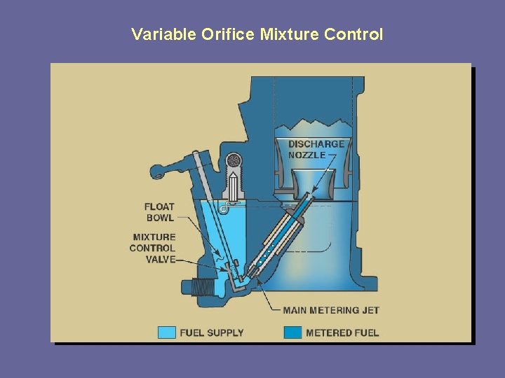
The Aircraft Float Carburetor • Mixture Control System • Back Suction Mixture Control Varies the pressure in the float chamber between atmospheric and a pressure slightly below atmospheric. • Variable Orifice Mixture Control Changes the size of the opening between the float bowl and the discharge nozzle.
Back Suction Mixture Control
Variable Orifice Mixture Control
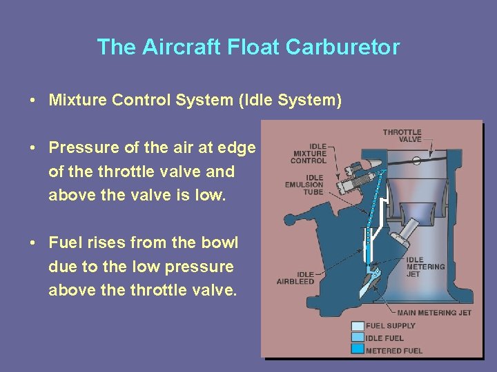
The Aircraft Float Carburetor • Mixture Control System (Idle System) • Pressure of the air at edge of the throttle valve and above the valve is low. • Fuel rises from the bowl due to the low pressure above throttle valve.
The Aircraft Float Carburetor • Acceleration System • Picks up fuel from bowl at idle and discharges it through the pump discharge when the throttle is opened.
The Aircraft Float Carburetor • Power Enrichment System • Removes some of the heat by enriching the fuel -air mixture at full throttle. • Some only provide full power enrichment when the throttle is all the way open. • When takeoff power is required, throttle should be opened fully.
The Aircraft Float Carburetor • Float Carburetor Preflight Inspection • No fuel leaking • Sump all drain points
The Aircraft Float Carburetor • Carburetor Icing And Heat Use • Carburetor ice means ice at any location in the induction system. – Impact ice – Fuel ice – Throttle ice
Carburetor Ice • Impact ice • Formed by the impingement of moisture-laded air at temperatures below freezing onto the elements of the induction system which are at temperatures below freezing. • Air scoop, heat valve, carburetor air screen, throttle valve and metering elements.
Carburetor Ice • Fuel Ice • Forms when any air or fuel entrained moisture reaches a freezing temperature as a result of cooling of the mixture by fuel vaporization. – Cooler air holds less water vapor and the excess water is precipitated in the form of condensation. – Condensate freezes. – Can occur at ambient temperatures well above freezing.
Carburetor Ice • Throttle ice • Formed at or near a partly closed throttle when water vapor in the induction air condenses and freezes due to the expansion cooling and lower pressure at the throttle. • Temperature drop normally does not exceed 5° F. • How is carburetor ice formation prevented?
Fuel Injection Systems
Advantages • • Even fuel/air mixture distribution More power Less fuel Less problems with carburetor ice
Differences from float carburetors • Fuel Injection: Deposits a continuous flow of fuel into the induction system near the intake valve just outside of the cylinder. • Carburetor: The correct amount of fuel is metered into the airflow.
Two Types • Bendix RSA • Teledyne-Continental
Bendix Fuel Injection System • Uses a venturi and air diaphragm to develop a fuel metering force. – Impact tubes sense total pressure of air entering the engine. (Dynamic + Static) – Venturi senses its velocity. – Both combine to move the air diaphragm proportionally to the amount of air ingested into the engine.
Fuel Metering Force • Pressure drop across the orifice in the fuel injector nozzles. • Position of the ball valve in its seat.
Idle System • Constant head spring pushes against the air diaphragm and forces the ball valve off its seat. (at low air flow) • As air flow increases the air diaphragm moves over.
Idle RPM/Mixture Control • Limit the amount of air allowed to pass the throttle valve. • Limit the amount of fuel to flow to the discharge nozzles.
Flow Divider • At idle a spring holds the flow divider valve closed to oppose fuel flow until fuel pressure off-seats valve. • Creating down stream pressure for the fuel control. • Provides cut off of fuel at idle cut off.
The Teledyne-Continental Fuel Injection System • Meters fuel as a function of engine RPM. • No Venturi • Special engine driven pump produces the fuel metering pressure. (constant displacement pump)
Mixture control • Manual mixture control valve • Variable selector • Fuel is bypassed back to the tank.
Throttle control • Controls air valve and fuel valve. • Fuel valve is variable orifice
Fuel Manifold Valve • • “Spider” Similar to the flow divider of Bendix Distributes fuel evenly Provides positive shut off at idle cut-off position.
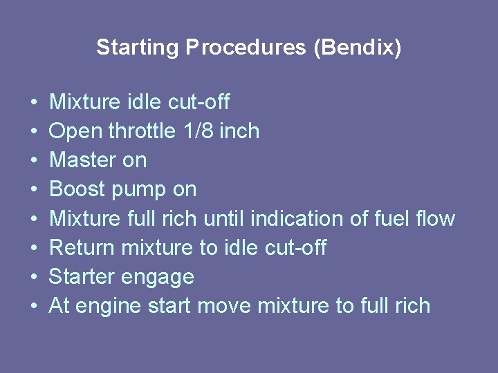
Starting Procedures (Bendix) • • Mixture idle cut-off Open throttle 1/8 inch Master on Boost pump on Mixture full rich until indication of fuel flow Return mixture to idle cut-off Starter engage At engine start move mixture to full rich
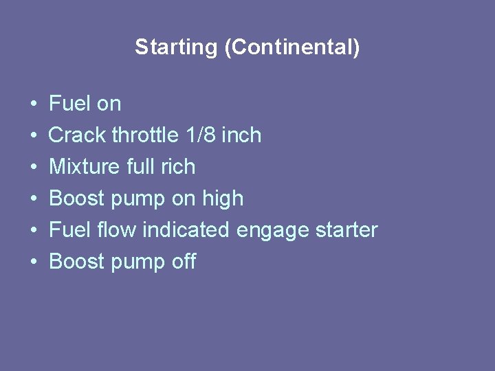
Starting (Continental) • • • Fuel on Crack throttle 1/8 inch Mixture full rich Boost pump on high Fuel flow indicated engage starter Boost pump off
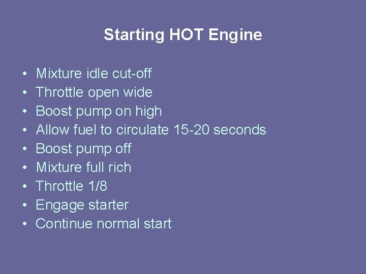
Starting HOT Engine • • • Mixture idle cut-off Throttle open wide Boost pump on high Allow fuel to circulate 15 -20 seconds Boost pump off Mixture full rich Throttle 1/8 Engage starter Continue normal start
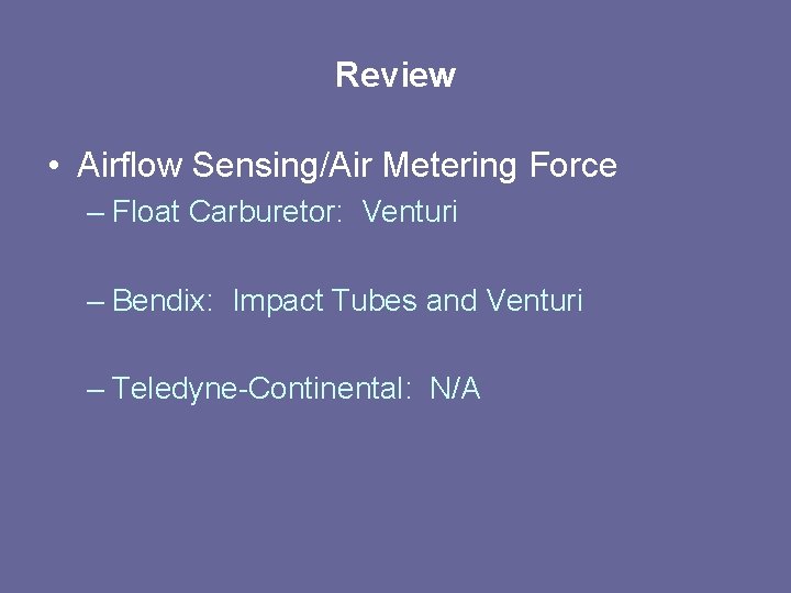
Review • Airflow Sensing/Air Metering Force – Float Carburetor: Venturi – Bendix: Impact Tubes and Venturi – Teledyne-Continental: N/A
• Fuel Metering force – Float: Pressure Diff. between venturi and float chamber – Bendix: Balance between the air and fuel forces holds valve off its seat a stabilized amount for and given air flow. – Teledyne-Continental: Engine RPM
• Mixture Control – Float: Back suction, Variable orifice, Needle valve at idle. – Bendix: Valve in the fuel control regulates the amount of fuel that can flow to main metering jet. – Teledyne-Continental: Variable Selector.