Inputs INPUTS Outputs OUTPUTS A B C F

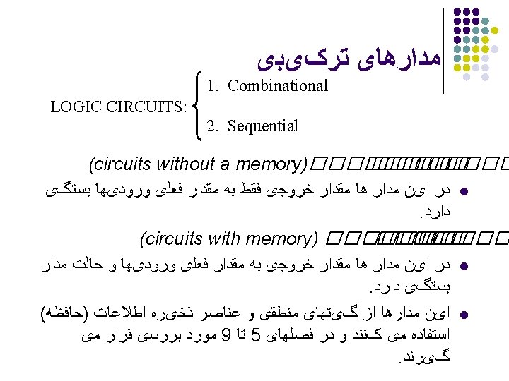

آﻨﺎﻟیﺰ ﻣﻨﻄﻖ ﺗﺮکیﺒی Inputs INPUTS Outputs OUTPUTS A B C F 1 F 2 0 0 1 1 0 1 0 1 0 1 1 0 0 0 1 1 1

Verilog ﻣﺪﺍﺭﻫﺎی ﺗﺮکیﺒی – کﺪ //Example 4 -10 //--------------------- //Gate-level description of combinational circuit module analysis (A, B, C, F 1, F 2); input A, B, C; output F 1, F 2; wire T 1, T 2, T 3, F 2 not, E 1, E 2, E 3; or g 1 (T 1, A, B, C); and g 2 (T 2, A, B, C); and g 3 (E 1, A, B); and g 4 (E 2, A, C); and g 5 (E 3, B, C); or g 6 (F 2, E 1, E 2, E 3); not g 7 (F 2 not, F 2); and g 8 (T 3, T 1, F 2 not); or g 9 (F 1, T 2, T 3); endmodule

ﻣﺪﺍﺭﻫﺎی ﺗﺮکیﺒی – کﺪ Verilog //Stimulus to analyze the circuit module test_circuit; reg [2: 0]D; *input specified with a 3 -bit reg vector D: 0 2 wire F 1, F 2; *outputs analysis circuit(D[2], D[1], D[0], F 1, F 2); *D[2]=A, D[1]=B, D[0]=C initial begin D = 3'b 000; *D is a 3 -bit vector initialized to 000 repeat(7) *The repeat loop gives the 7 binary numbers after 000 #10 D = D + 1'b 1; *D is incremented by 1 after 10 ns end initial $monitor ("ABC = %b F 1 = %b F 2 =%b ", D, F 1, F 2); *Display truth table endmodule Simulation Log: ABC = 000 F 1 = 0 F 2 = 0 ABC = 001 F 1 = 1 F 2 = 0 ABC = 010 F 1 = 1 F 2 = 0 • •

 Copyright: Tylavsky, Arizona State University")
ARITHMETIC LOGIC UNIT (ALU) Copyright: Tylavsky, Arizona State University

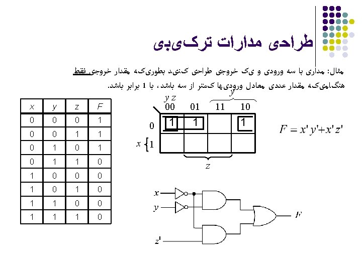
 ﺟﻤﻊ کﻨﻨﺪﻩ کﺎﻣﻞ Inputs INPUTS A B C 0 0 1 1")
(full adder) ﺟﻤﻊ کﻨﻨﺪﻩ کﺎﻣﻞ Inputs INPUTS A B C 0 0 1 1 0 1 0 1 Outputs OUTPUTS F 1 F 2 0 1 1 0 0 0 1 1 1 C

چﻬﺎﺭ ﺑیﺘی Full-adder 3 2 1 0 i 0 1 1 0 Ci 1 0 1 1 Ai 0 0 1 1 Bi 1 1 1 0 Si 0 0 1 1 Ci+1

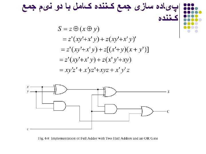
چﻬﺎﺭ ﺑیﺘی – کﺪ Full-adder verilog //Gate-level hierarchical description of 4 -bit adder // Description of half adder (see Fig 4 -5 b) module halfadder (S, C, x, y); input x, y; output S, C; //Instantiate primitive gates xor (S, x, y); and (C, x, y); endmodule //Description of full adder (see Fig 4 -8) module fulladder (S, C, x, y, z); input x, y, z; output S, C; wire S 1, D 2; //Outputs of first XOR and two AND gates //Instantiate the halfadder HA 1 (S 1, D 1, x, y), HA 2 (S, D 2, S 1, z); or g 1(C, D 2, D 1); endmodule

چﻬﺎﺭ ﺑیﺘی – کﺪ Full-adder verilog //Description of 4 -bit adder (see Fig 4 -9) module _4 bit_adder (S, C 4, A, B, C 0); input [3: 0] A, B; input C 0; output [3: 0] S; output C 4; wire C 1, C 2, C 3; //Intermediate carries //Instantiate the fulladder FA 0 (S[0], C 1, A[0], B[0], C 0), FA 1 (S[1], C 2, A[1], B[1], C 1), FA 2 (S[2], C 3, A[2], B[2], C 2), FA 3 (S[3], C 4, A[3], B[3], C 3); endmodule
- Slides: 18