ILC Damping Rings Status and Plans Mark Palmer


- Slides: 31

ILC Damping Rings: Status and Plans Mark Palmer Junji Urakawa Andy Wolski ILC 08 UIC, Chicago, 20 November 2008 Global Design Effort 1

Program Outline 2008 Minimum Machine Technical Design, and Costing Specify tasks. Specify scope. TDP Phase I 2009 Perform studies. Start 2010 TDP Phase II 2010 – 2012 Damping Rings Summary, ILC 08 Perform technical design and costing work in support of revising the baseline configuration. Critical R&D Continue critical R&D for cost reduction and risk mitigation: • electron cloud; • fast kickers; • low-emittance tuning. Revise baseline configuration. Complete work for TDR (end 2012). Global Design Effort Complete critical R&D. 2

Critical R&D: Electron Cloud DA NE KEKB Cesr. TA E-Cloud Collaboration: • ANL • Cornell • FNAL • INFN/LNF • KEK • LBNL • SLAC Damping Rings Summary, ILC 08 Global Design Effort 3

Electron Cloud: Goals 1. Collect data to validate the simulation codes in the parameter regime of the ILC damping rings. – We need to understand, and be able to predict, build-up of the cloud under a variety of conditions. – We need to understand, and be able to predict, beam dynamics with e-cloud in ultra-low emittance regime. 2. Develop effective mitigation techniques. – Mitigation methods needed for drifts, dipoles, wigglers. – Methods must be demonstrated and adverse consequences understood. Damping Rings Summary, ILC 08 Global Design Effort 4

Cesr. TA E-Cloud Program (1) • CESR has been reconfigured to allow operation at low horizontal emittance (few nm). – Includes re-locating wigglers at zero-dispersion points in the lattice. – Commissioning run has just been successfully completed. Damping Rings Summary, ILC 08 Global Design Effort 5

Cesr. TA E-Cloud Program (2) Photodiode array for fast x-ray beam size monitor. • Instrumentation and diagnostics have been upgraded: – specialised e-cloud diagnostics developed and installed (e. g. retarding field analysers in wiggler vacuum chamber); – upgraded fast feedback system to maintain beam stability with short bunch separation; – improved alignment systems and high-performance BPM system to allow tuning for ultra-low emittance; – fast x-ray monitor (under development) for turn-by-turn beam size measurement with micron resolution. Damping Rings Summary, ILC 08 Retarding field analysers for electron cloud measurements in wiggler chambers. Global Design Effort 6

Cesr. TA E-Cloud Program (3) Damping Rings Summary, ILC 08 Global Design Effort 7

Cesr. TA E-Cloud Program (4) Simulation studies aim to validate modelling tools. Simulation of RFA signal (right) compared to data (left). Simulation of electron cloud distribution in 2 D field (right) and 3 D field (left). Damping Rings Summary, ILC 08 Global Design Effort 8

E-Cloud Studies at KEKB (1) Clearing electrode for mitigation in magnetic field, with RFA. Damping Rings Summary, ILC 08 Global Design Effort 9

E-Cloud Studies at KEKB (2) Application of voltage on clearing electrode leads to a dramatic reduction in electron cloud density. B = 0. 77 T -500 V Ie [A] ele V 10 -5 10 -6 10 -7 c [V ] Velec = 0 V 10 -8 10 -9 Damping Rings Summary, ILC 08 +500 V Global Design Effort 10

E-Cloud Studies at KEKB (3) Grooved chambers (manufactured by SLAC) are presently being tested. Damping Rings Summary, ILC 08 Global Design Effort 11

E-Cloud Studies at DA NE Multibunch instability caused by electron cloud. Simulations consistent with main observations. 60 equispaced bunches Beam current 1. 2 A Growth time ~ 100 turn Damping Rings Summary, ILC 08 Global Design Effort 12

Fast Kicker R&D • The goal is to develop and demonstrate a highreliability fast kicker that meets the ILC specifications for damping ring injection and extraction. Pulse amplitude 10 k. V Bunch spacing 3 ns Pulse repetition rate 6. 6 MHz Pulse stability ~ 0. 1% • R&D program includes activities at SLAC, INFN/LNF and KEK. Damping Rings Summary, ILC 08 Global Design Effort 13

Fast Injection/Extraction Kickers: SLAC • Researchers at SLAC are investigating two possible technologies: MOSFET array, and DSRD fast switch. • Both technologies provide attractive characteristics. • A hybrid pulser may be the best solution. Damping Rings Summary, ILC 08 Global Design Effort 14

Fast Injection/Extraction Kickers: LNF Fast, high-power pulsers approaching ILC DR specifications are being tested as part of DA NE upgrade program. 45 k. V 5 ns pulse (FID) DA NE stripline kicker designs are being modified for devices to be installed for testing in ATF. Damping Rings Summary, ILC 08 Global Design Effort 15

Fast Injection/Extraction Kickers: KEK • Goal is to achieve single-bunch extraction from ATF DR for ATF 2, demonstrating ILC damping ring performance specifications. • Fast (FID) pulsers have 10 k. V peak output, rise time around 2 ns. • Strip line kickers have been manufactured and show good impedance characteristics. Damping Rings Summary, ILC 08 Global Design Effort 16

Low-Emittance Tuning • ILC damping rings are specified to operate with 2 pm vertical emittance. • Swiss Light Source has recently achieved 3 pm. • Low-emittance tuning program includes work at: – ATF: motivated by ATF 2, studies of fast ion instability, and demonstration for ILC damping rings; – Cesr. TA: motivated by studies of electron cloud in ultralow emittance regime; – Cockcroft Institute: in support of ATF and Cesr. TA programs, and ILC damping rings design. • Issues include: alignment and stabilisation specifications; diagnostics and instrumentation functionality and performance; design of coupling correction system; development of effective tuning techniques. . . Damping Rings Summary, ILC 08 Global Design Effort 17

Low-Emittance Tuning: KEK Remote participation in machine studies is made effective by use of Control Room Web Cam and Skype. Damping Rings Summary, ILC 08 Global Design Effort 18

Low-Emittance Tuning: Cesr. TA BPM gain mapping • Determine BPM gain errors. • Apply sequence of corrections. • Further characterise BPM and coupling errors. Damping Rings Summary, ILC 08 • • Beam-based alignment Correct orbit Correct phase / coupling Correct vertical dispersion Orbit response matrix analysis Global Design Effort 19

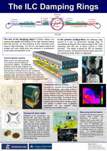
Damping Rings Design and Costing (1) Present baseline: DCO lattice • • Arcs consist of a total of 192 FODO cells Flexibility in tuning momentum compaction factor, given by phase advance per arc cell: – 72 phase advance: p=2. 8 10 -4 – 90 phase advance: p=1. 7 10 -4 – 100 phase advance: p=1. 3 10 -4 6476 m 5 Ge. V • • No changes in dipole strengths needed for different working points. Racetrack structure has two similar straights containing: – – – Cesr. TA Web. Ex, 14 October 2008 injection and extraction in opposite straights phase trombones circumference chicanes rf cavities "doglegs" to separate wiggler from rf and other systems wiggler Global Design Effort 20

Damping Rings Design and Costing (2) Significant progress is being made with a CAD model for the present baseline lattice. Tapered Vessel Pumping Port Ante-Chambered Vessel Straight Cylindrical Vessel Tapered Vessel Gate Valves Electron Vessel BPM Station (Electron) Gate Valves Positron Vessel BPM Station (Positron) Damping Rings Summary, ILC 08 Global Design Effort 21

Damping Rings Design and Costing (3) Development of the CAD model provides essential information for: • • • technical systems development (vacuum, conventional facilities. . . ); costing and value engineering; beam dynamics studies (low emittance tuning, e-cloud. . . ) Vessel with antechamber for e-cloud mitigation. BPM chamber with position encoders. BPM/bellows will contribute to machine impedance. Damping Rings Summary, ILC 08 Global Design Effort 22

Impedance Model: BPM/bellows/tapers From the impedance model we can evaluate: + Haissinski Tracking Charge density (m-1) • potential well distortion; • HOM heating; • instability thresholds. Bunch population 109 z (m) Charge density (m-1) Bunch population 1. 3× 10¹⁰ z (m) Cesr. TA Web. Ex, 14 October 2008 Global Design Effort 23

“Minimum Machine” Studies ECM (Ge. V) Particles per bunch, N (× 1010) Bunches per pulse, nb Pulse repetition rate (Hz) Peak beam power, Pb (MW) gex (mm) gey (nm) bx (cm) by (mm) Traveling focus sx (nm) sy (nm) sz (mm) Beamstrahlung* d. E/E Luminosity* (× 1034 cm-2 s-1) Nom. RDR 500 2. 0 2625 5 10 40 2. 0 0. 4 No 640 5. 7 300 0. 023 2. 0 Low P RDR 500 2. 0 1320 5 5. 3 10 36 1. 1 0. 2 No 474 3. 8 200 0. 045 1. 7 new Low P 500 2. 0 1320 5 5. 3 10 36 1. 1 0. 2 Yes 474 3. 8 300 0. 036 1. 9 N. J. Walker, PAC Meeting, October 2008 Damping Rings Summary, ILC 08 Global Design Effort 24

“Minimum Machine” Studies • Main implication for the damping rings is that the “low power” parameter set makes a 3 km circumference feasible. – Number of bunches in the ring is halved. – Average current and bunch separation remain constant. • Reducing the circumference makes it possible to contemplate also reducing the beam energy. – Maybe reduce from 5 Ge. V to 4. 6 Ge. V, or 4. 2 Ge. V. Reduces longitudinal emittance, with benefits for the bunch compressors. Reduces amount of wiggler, rf, magnet power, etc. L Injected beam sizes becomes larger. L Beam becomes less robust against collective effects. Damping Rings Summary, ILC 08 Global Design Effort 25

“Minimum Machine” Studies • We have two lattices that can be used as a basis for 3 km damping ring studies. . . • . . . one of them produced by replacing the arc cells in the present baseline lattice, with cells based on those used in Super. B. Damping Rings Summary, ILC 08 Global Design Effort 26

Plans for TDP-I/Minimum Machine 1. Continue critical R&D: • electron cloud; fast kickers; low emittance tuning. 2. Produce technical evaluation and cost comparison of 6 km and 3 km damping ring options, by end 2009, to support possible new baseline. 3. Continue technical design and costing work for TDR. Task Responsibility Modify/develop 3 km damping ring lattice design. Korostelev/Biagini Evaluate dynamics in 3 km damping ring. Korostelev/Biagini Develop lattice designs for injection/extraction lines. Guiducci Continue to develop impedance model. Korostelev/Marcellini Develop and maintain CAD models. Lucas Update and maintain cost estimates. Lucas Specify and cost power distribution system. Palmer/Bellomo Damping Rings Summary, ILC 08 Global Design Effort 27

LC Damping Rings Collaboration • Differences in linac technologies drive damping rings to different configurations in ILC and CLIC, however. . . • . . . there a number of high-priority issues that are common for both projects: – electron cloud mitigation; – ultra-low emittance tuning and preservation. • A first step toward closer collaboration has already been taken, in coordinating CLIC and ILC damping rings Web. Ex meetings. • A joint working group on damping rings is now being established, convened by Yannis Papaphilippou and Mark Palmer. Damping Rings Summary, ILC 08 ILC Energy (Ge. V) CLIC 5 2. 4 6476 365 27005400 312 Particles/bunch (1010) 2. 0 -1. 0 0. 37 Damping time x (ms) 21 1. 5 Emittance gex (nm) 4200 381 Emittance gey (nm) 20 4. 1 Momentum compaction (10 -4) 1. 3 -2. 8 0. 80 Energy loss/turn (Me. V) 8. 7 3. 9 Energy spread 1. 3 x 10 -3 1. 4 x 10 Bunch length (mm) 9. 0 - 6. 0 1. 53 17 - 32 4. 1 650 2000 Circumference (m) Bunch number RF Voltage (MV) RF frequency (MHz) Global Design Effort -3 28

LC Damping Rings Collaboration The CLIC-ILC working group on damping rings will: • develop synergies and collaborate in beam dynamics and technical issues of common interest in damping ring design; • promote the use of common research approaches and studies when possible, including numerical tools; • enable researchers to take advantage of existing test facilities or storage rings and participate in a common experimental program; • trigger communication, establish links between the two communities, share knowledge and document common work. A more detailed mandate is being drafted. Damping Rings Summary, ILC 08 Global Design Effort 29

Final Words • The goals for the damping rings R&D program are clearly defined: 1. Demonstrate performance specifications in the critical areas of electron cloud, fast kickers, and low-emittance operation. 2. Produce technical performance and cost comparisons of present baseline (6 km) and possible “minimum machine” (3 km) damping ring configurations. 3. Develop design and costs information in support of the Technical Design Report. • There is more activity and progress than I would have thought possible given the recent funding situation. • Steps are being taken to establish closer collaboration between CLIC and ILC damping ring groups, and thereby get maximum benefit from limited resources. Damping Rings Summary, ILC 08 Global Design Effort 30

Thanks and apologies to. . . David Alesini Floyd Antz Marica Biagini Craig Burkhart Joe Calvey Christine Celata Norbert Collomb Ed Cook John Corlett Theo Demma Alessandro Drago Gerry Dugan Miguel Furman Susanna Guiducci Damping Rings Summary, ILC 08 Kai Hock Kathy Harkay Walter Hopkins Dennis Kamp Alexei Kardo-Sysoev Maxim Korostelev Anatoly Krasnykh Kiyoshi Kubo Shigeru Kuroda Ray Larsen Yulin Li John Lucas Oleg Malyshev Fabio Marcellini Dawn Munson Takashi Naito Toshiaki Okugi Kosmas Panagiotidis Yannis Papaphilippou Mauro Pivi David Rubin David Sagan Stefano de Santis Jim Shanks Yusuke Suetsugu Tao Tang Nobuhiro Terunuma Mark Woodley Global Design Effort 31
 Ilc and slc
 Zsuits
 Ilc 2013
 Ilc 150 eth
 Zora rutar ilc
 Boom chicka boom
 Kaon cp violation
 Ilc europe
 Mark j palmer
 Rrr classification
 Measuring instruments definition
 Heavy damping
 Unececarry
 Air friction damping diagram
 Heavy damping graph
 Peak time
 Heavy damping equation
 Muscle tone
 Damping coefficient c
 Damper in suspension system
 Frequency of oscillation
 Measuring instrument
 Roll damping
 How are written codes used in each of these posters
 Bed blocks comfort device
 What is written codes
 Pistons rings and connecting rods
 Copyright
 Dmf index
 Loftus and palmer
 Bachman and palmer 1996
 Joslin class rings
