I 0103 FGP and Automation Flight Guidance Panel


- Slides: 26

I 0103 - FGP and Automation

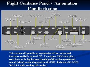
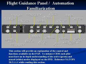
Flight Guidance Panel • PF owns FGP when AP engaged, PM owns FGP at all other times. • Each pilot owns their own course knob For a more detailed description of the Flight Guidance System and CRM Callouts reference NATOPS Chapters 20 and 22.

Automation Pyramid 1. FD/AP-CDI Coupled to LNAV/VNAV or ILS Implied - Lower Workload & Higher Situational Awareness 2. FD/AP-CDI Coupled to FMS/VOR/TAC/LOC 3. FD/AP-CDI Coupled to HDG/CRS 1. FD/Manual-CDI Coupled to LNAV/VNAV or ILS 2. FD/Manual-CDI Coupled to FMS/VOR/TAC/LOC 3. FD/Manual-CDI Coupled to HDG/CRS FD/AP-CDI Level 4 4. FD or FD/AP GCA Coupled to HDG and/or vertical 1. Manual-CDI ILS 2. Manual-CDI GPS/VOR/TAC/LOC 3. Manual-CDI Coupled to HDG/CRS 1. Manual GCA 2. Manual needle-only VOR/TAC 3. Manual NDB 4. Manual Visual FD/Manual-CDI Level 3 Manual-CDI Level 2 Manual Level 1

Flight Director FD – Engages/Disengages the on-side Flight Director. Both flight directors may also be engaged by: Autopilot engagement, manual selection of goaround mode, or pushing a vertical/lateral mode button. The FD can be used with or without the AP engaged.

Flight Guidance System The Flight Director (FD) command bars and FD/AP mode Display messages show on the PFD above the attitude display when either FD is selected, or the autopilot is engaged. • The active modes show in green in the upper field. The armed modes show in white in the lower field. • Modes will belong in one of three categories and be displayed left to right: Lateral, AP Engagement, and Vertical. • All active vertical modes flash for 5 seconds when they first come into view, and then show steady.

Flight Guidance Transfer • Push the CPL button on the FGP to transfer flight guidance. • Flight guidance transfer dictates which Flight Guidance Computer is in control. • The FGC navigates off the primary source for the. WARNING respective side. • With the flight director on, transferring flight guidance will change the FD modes to Pitch and Roll. • This could also occur if the FD engaged to the primary nav source and the primary nav source is changed. • The aircrew must reselect the appropriate lateral and vertical guidance. Caution: The Pilot with BARO Mins selected must have the CPL arrow pointing to the respective side or the PSA will not be capable of selecting the BARO mins.

Course Knob The Course (CRS) Knob controls the pilot/copilot-side VHF Omnidirectional Radio Range (VOR) or Tacan (TAC) Localizer (LOC) course pointer. PUSH DIRECT Button The PUSH DIRECT button, located in the center of the CRS knob, selects a direct course to the VOR station or Tacan that is the active NAV source on the copilot-side PFD. Note If FMS is the active NAV source, then the CRS knob is inactive.

Yaw Damper YD – Engage or disengage the Yaw Damper. The AP/YD DISC switch-bar on the FGP must be in the up position. The YD can be engaged with out engaging the autopilot. If the AP button is pushed, both autopilot and YD are engaged. Disengaging the YD also disengages the AP. AP WARNING The AP or GA button does not disconnect the Yaw Damper, which will result in lack of directional control during landing.

AUTOPILOT AP – Autopilot engagement occurs if: the AP/YD DISC switch-bar on the FGP is in the up position, no unusual attitudes, rates, or accelerations are present. Pushing the AP button with Autopilot engaged, disengages the AP but will leave the YD on. Engagement of the AP will engage the YD. The aircraft should be trimmed out prior to engaging the AP.

HEADING MODE • HDG – Press the HDG button to select heading as the lateral mode. • Turn the heading knob to desired heading. • Press the heading knob to sync heading bug to current aircraft heading. • The ½ Angle of Bank function automatically come on at 18, 500 ft or can be manually selected on the FGP. This limits the FD angle to 12. 5 degrees.

NAVIGATION MODE • NAV – Navigation mode captures and tracks a pilot selected course from the active NAV source. NAV mode provides only lateral guidance and must be used for non-precision approaches. (Except LNAV/VNAV)

Approach Mode • APPR – Approach mode generates commands to capture and track the selected localizer or FMS course and vertical Glideslope (GS) or Vertical Glidepath (VGP). • ILS – Upon tuning the frequency and setting the course APPR Mode will arm LOC and GS which will be captured by the FGC once established. • RNAV (LNAV/VNAV) – Mode will capture in FMS for the lateral mode and Vertical Glide Path (VGP) for the vertical mode. VGP is a mode that was designed to let an FMS approach operate like a normal ILS approach. • Once vertical guidance (GS or VGP) is captured the PM can set heading and climb out altitude for the missed approach.

Altitude • ALT – Selects ALT hold mode (pushon/push-off) Maintains existing pressure altitude. • The ALT knob changes desired altitude.

Altitude • ALTS – Altitude pre-selector (PSA) captures the target altitude. Available when the following modes are not active: GS approach mode, GP approach mode, altitude hold mode. • ALTS will automatically arm when the PSA knob is turned to an altitude other than the current altitude and a vertical guidance mode (FLC or V/S) is selected.

VERTICAL SPEED • VS – Vertical Speed is used in conjunction with the pitch wheel to set desired rate of climb or descent. If VS is selected while in climb or descent the FD will capture the current aircraft Vertical Speed. • Note – VS will prioritize the selected vertical speed over airspeed.

FLIGHT LEVEL CHANGE • FLC – Flight Level Change maintains the airspeed reference provided the command yields a vertical speed greater than 100 fpm toward the preselected altitude. • The FD will pitch for the selected airspeed and power will directly control rate of climb or descent.

Vertical Navigation • VNAV –When a desired altitude is loaded and executed in the FMS, VPATH is armed. When the aircraft intercepts the desired path, VPATH is captured and the aircraft will descend via FMS calculated descent rate. • The altitude pre-selector must be at or below the FMS altitude for the aircraft to continue descent. The altitude pre-selector will take precedence unless VGP or GS is captured as the vertical mode.

Vertical Navigation VNAV for the T-44 C has essentially two modes: Enroute: Can be used for SID’s, STARS, and descents Terminal: Used for LNAV/VNAV approaches VNAV uses a vertical path to comply with all FMS altitude and speed restrictions. The altitude pre-selector will take priority over FMS altitudes.

VGP VS. VPATH • Whenever VGP is active, the preselected altitude will be disregarded by the flight director. Therefore, the flight director will not level off at the baro mins. Instead, it will continue on a 3 degree glide path to the runway. • In NAV mode (APPR not selected), VPATH is active and will level off at the pre-selected altitude.

GO AROUND BUTTON • GO AROUND – Selected on throttle or CP yoke. Go around mode disengages the autopilot, selects both flight directors to GA, sequences the FMS to the go around procedure, sets the heading reference to the heading that existed at takeoff or go around, and sets the pitch reference to 7 degrees nose up. • The GA button will cycle the FMS to the missed approach on an RNAV. Warning The AP or GA button does not disconnect the Yaw Damper.

FLIGHT DIRECTOR PHILOSOPHY • The mantra for flight director and autopilot usage is select and verify. Ensure that the proper flight mode is selected then verified on the Flight Guidance System Display to confirm that the anticipated mode of operation is either activated or in sequence for activation. • Use the term “set” for headings, altitudes, speeds and vertical speeds. • Use the term “select” for mode selection (HDG, NAV, APPR, VNAV, FLC, VS etc. ).

FLIGHT DIRECTOR PHILOSOPHY • Flight directors are garbage in = garbage out systems, meaning if false information is selected it can be a distraction or dangerous to flight operation. • Good knowledge and understanding of the FGS will allow you to move up the Automation Pyramid when more focus is needed on mission or emergencies. • If the flight director or autopilot is detracting from safety of flight, turn them off and fly manually. • Do not delay the execution of a clearance because of slow actuation of the Flight Guidance Panel.

• It is important to brief automation levels for critical phases of flight. From briefing automation on takeoff, an approach, or a go around it is good CRM to brief before executing the phase of flight. This allows a lower chance of miscommunication especially when the flight deck is busy. BRIEFING AUTOMATION LEVELS • Briefing the expected modes will ensure timely and accurate FGP operation and consequently add to CRM and safety. • For initial takeoff, touch and go, or go around the autopilot shall not be engaged below 400’. (NATOPS)

Flight Director Techniques PAR/ASR: Use heading mode (PF setting if coupled, PM if uncoupled). Set mins and use FLC 120 kts when on GP. Adjust power to control rate of descent based on the PAR controller or ASR recommended altitudes. RNAV (LNAV/VNAV): Use AVP once cleared for the approach. Select Approach mode, VNAV, and then pre-set mins. RNAV (LNAV): Use NAV mode once cleared on a publish segment of the approach. Use PSA to set step down altitudes along with FLC or VS. VOR/TAC: Use heading mode and NAV mode as required along with setting the proper course (you will need to set the outbound course when using the FD on a FPT). Use PSA to set step down altitudes along with FLC or VS. *Only a few examples, there are many different techniques.

Flight Director Example Go around execution PF: “Go around (select GA button), gear up, flaps up, props 1900. PF: (passing 400’) “Set heading 030, set altitude to 3000’, select heading mode, select flight level change, set 150 KTS. ” PM: “ 030 set, heading mode, 3000 set, FLC, 150 KTS set. ” Go around execution (Published Missed RNAV) PF: “Go around (select GA button), gear up, flaps up, props 1900. (FMS as NAV source) PF: “Select NAV mode, set Alt to 2000’, select Flight Level Change 150 KTS. ” PM: “NAV mode selected, 2000 set, FLC, 150 KTS set, ” Refer to NATOPS Chapter 22 for an all-inclusive list of Callouts.

Questions?
 Flight guidance panel
 Extra military instruction examples
 Vervolganamnese
 Continuous panel vs discontinuous panel
 Zıt panel nedir
 Lingualized occlusion vs balanced occlusion
 What is the purpose of direct and indirect guidance
 Fight flight freese
 How to reorder artboards in illustrator
 Triple 'f' of gland for flight, fright and fight is
 Flight mechanics problems and solutions
 Equation for drag
 Flight information display system and open source
 Frisbee ballon
 Aeroplane flight training manual
 Siemens energy automation
 Etl extract transform load
 Difference between counselling and advice
 Missouri comprehensive guidance and counseling program
 Digital advice and guidance
 History of guidance and counseling in the philippines pdf
 Difference between counselling and guidance
 Principles of guidance according to crow and crow
 National and local guidance on falls prevention
 Structured guidance and supports
 Organization and administration of guidance
 Direct and indirect guidance chapter 14

