GSM ARCHITECTURE GSM networks are made up of

, base station")
: This consists of the mobile")

 ■ There are three main types of ME. These are listed")
: This is the telephone number of")
 ■ The GSM BSS is the equipment located at")


 ■ The MSC is included in the GSM system")
 ■ The HLR is the reference database for subscriber parameters")


- Slides: 21
GSM ARCHITECTURE
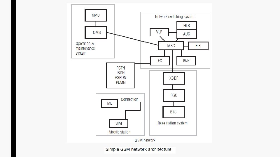
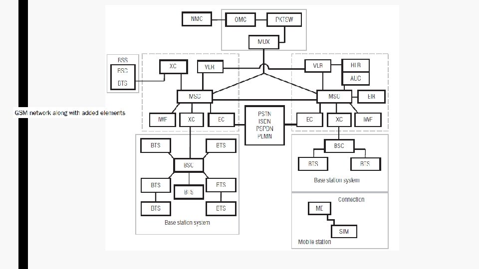
■ GSM networks are made up of mobile service switching centres (MSC), base station systems (BSS), and MS. These three entities can be broken down further into smaller entities. ■ With the MSC, BSS, and MS, we can make calls, receive calls, perform billing, and so on, as any normal PSTN network would be able to do. ■ The only problem for the MS is that all the calls made or received are from other MSs. Therefore, it is also necessary to connect the GSM network to the PSTN. ■ MSs within the cellular network are located in “cells”. These cells are provided by the BSSs. ■ GSM network consists of several functional entities whose functions and interfaces are defined. – The MS – The base station subsystem (BSS) – The network switching subsystem (NSS) – The operation and maintenance/support system (OSS) ■ The GSM network adds some other components that include the functions of the databases and messaging systems.
Principle components of GSM Network ■ Mobile station (MS): This consists of the mobile telephone, fax machine, and so on. This is the part of the network that the subscriber will see. ■ Base station system (BSS): This is the part of the network which provides the radio interconnection from the MS to the land-based switching equipment. ■ Network switching system (NSS): This consists of the MSC and its associated system-control databases and processors together with the required interfaces. This is the part which provides for interconnection between the GSM network and the public switched telephone network (PSTN). ■ Operations and maintenance system (OMS): This enables the network provider to configure and maintain the network from a central location.
1. The mobile station ■ The MS consists of two components: the mobile equipment (ME) and an electronic “smart card” called a subscriber identity module (SIM). ■ The ME is the hardware used by the subscriber to access the network. ■ The hardware has an identity number associated with it, which is unique for that particular device and permanently stored in it. This identity number is called the international mobile equipment identity (IMEI) and enables the network operator to identify ME which may be causing problems on the system. ■ The SIM is a card which plugs into the ME. This card identifies the MS subscriber and also provides other information regarding the service that the subscriber should receive. ■ The subscriber is identified by an identity number called the international mobile subscriber identity (IMSI). ■ ME may be purchased from any store but the SIM must be obtained from the GSM network provider. ■ Without the SIM inserted, the ME will only be able to make emergency calls. ■ The MS also acts as a receptor for SMS messages, enabling the user to toggle between the voice and data use.
Mobile equipment (ME) ■ There are three main types of ME. These are listed below: – Vehicle mounted: These devices are mounted in a vehicle and the antenna is physically mounted on the outside of the vehicle. – Portable mobile unit: This equipment can be handheld when in operation, but the antenna is not connected to the handset of the unit. – Hand portable unit: This equipment comprises of a small telephone handset not much bigger than a calculator. The antenna is connected to the handset. Subscriber identity module (SIM) ■ The SIM contains several pieces of information: – International mobile subscriber identity (IMSI): This number identifies the MS subscriber. It is transmitted over the air only during initialization. – Temporary mobile subscriber identity (TMSI): This number identifies the subscriber; it is periodically changed by the system management to protect the subscriber from being identified by someone attempting to monitor the radio interface. – Location area identity (LAI): Identifies the current location of the subscriber. The fields of LAI are (1) country code (CC): three decimal places; (2) mobile network code (MNC): two decimal places; (3) location area code (LAC): maximum five decimal places or maximum twice the 8 bits coded in hexadecimal (LAC < FFFF). – Subscriber authentication key (Ki): This is used to authenticate the SIM card.
– Mobile station international services digital network (MSISDN): This is the telephone number of the mobile subscriber. It is comprised of a country code, a network code, and a subscriber number. The MSISDN categories follow the international ISDN number plan and therefore have the following structure. ■ ■ ■ Country Code (CC): Up to three decimal places. National Destination Code (NDC): Typically two to three decimal places. Subscriber Number (SN): Maximum 10 decimal places. ■ The SIM can be protected by use of a personal identity number (PIN) password, similar to bank/credit charge cards, to prevent unauthorized use of the card. ■ The SIM is capable of storing additional information such as accumulated call charges. This information will be accessible to the customer via handset/keyboard key entry.
2. Base station subsystem (BSS) ■ The GSM BSS is the equipment located at a cell site and comprises of a combination of digital and RF equipment. ■ The BSS provides the link between the MS and the MSC. ■ Generally, the BSS communicates with the MS over the digital air interface and with the MSC via 2 Mbps links. ■ The BSS contains a BSC and one or more sub-standing BTSs. ■ The BSS is responsible for all functions related to the radio resources channel management. This includes the management of radio channel configuration with respect to use as speech, data, or signalling channels, allocation and release of channels for call setup and release, control of frequency hopping, and transmitted power at the MS. ■ The BSS is composed of the following: – Base transceiver station (BTS) – Base station controller (BSC) – Transcoder (XCDR)
Base transceiver station ■ The BTS contains a radio transceiver and antennas ■ BTS is placed in the centre of cell and handles the radio link protocols with MS. ■ A large number of BTSs are deployed in a large urban area. Number of transceivers with each BTS depends on density of users in the cell. Each BTS may contain 1– 16. ■ The BTS does the following functions: – Frequency and time synchronization – Encoding, encrypting, multiplexing, modulating, and feeding RF signals to the antenna. – Voice through full- or half-rate services – Timing advances – Transcoding and rate adaptation – Decoding, decrypting, and equalizing received signals – Random access detection – Uplink channel measurements
Base station controller ■ BSC is a switching device. It acts as a radio resource manager of BTSs as it performs the functions frequency hopping, radio channel setup, and handovers (both intercell and intracell). It also does the following functions: – Establishes connection between MSC and mobile – Manages the time slots and frequencies for the MS – Translates the voice channel (13 kps) over the radio link to standard channel (64 kbps) used by PSTN or ISDN – Allocates necessary time slots between the BTS and MS in its area – Reallocates frequencies among BTSs – Controls frequency hopping – Provides an interface to the operations and maintenance centre (OMC) for the BSS – Performs traffic concentration to reduce the number of lines from the MSC – Synchronizes frequency and time – Does time-delay measurements of received signals from the MS – Power management
The transcoder ■ The transcoder is used to compact the signals from the MS so that they are more efficiently sent over the terrestrial interfaces. ■ Although the transcoder is considered to be a part of the BSS, it is very often located closer to the MSC. ■ The transcoder is used to reduce the rate at which the traffic (voice/data) is transmitted over the air interface. ■ The transcoder converts the voice or data output from MSC into a form mentioned in GSM specification, that is it converts signals from 64 kbps to 16 kbps and vice versa.
3. Network switching subsystem ■ The NSS includes the main switching functions of the GSM network. ■ The main part of NSS is the mobile switching centre (MSC) which performs the switching of calls between the mobile and other fixed or mobile network users, as well as the management of mobile services such as authentication. ■ It also contains the databases required for subscriber data and mobility management. Its main function is to manage communications between the GSM network and other telecommunications networks. ■ The components of the NSS are listed below: – Mobile service switching centre (MSC) – Home location register (HLR) – Visitor location register (VLR) – Equipment identity register (EIR) – Authentication centre (AUC) – Interworking function (IWF) – Echo canceller (EC)
Mobile service switching centre (MSC) ■ The MSC is included in the GSM system for call-switching. Its overall purpose is the same as that of any telephone exchange. ■ The central component of the network subsystem is the MSC. The MSC performs the switching of calls between the mobile and other fixed or mobile network users, as well as the management of mobile services such as registration, authentication, location updating, handovers, and call routing to a roaming subscriber. ■ When the MSC provides the interface between the PSTN and the BSSs in the GSM network, it is known as a gateway MSC. ■ The functions carried out by the MSC are listed below: – Call processing: Includes control of data/voice call setup, supervision and release, inter-BSS, and inter-MSC handovers, and control of mobility management (subscriber validation and location). – Operations and maintenance support: Includes database management, management of radio resources, registration, location updating and traffic metering and measurement, and a man–machine interface. – Internetwork interworking: Manages the interface between the GSM network and the PSTN. – Billing: Collects call billing data.
Home location register (HLR) ■ The HLR is the reference database for subscriber parameters used for storage and management of new and old subscriptions. ■ It stores permanent data about subscribers which include service profile, activity status, and location information. ■ When a person gets a SIM, then all his information mentioned in subscription form is registered in HLR. ■ Usually, one HLR is developed for each GSM network for administration of subscriber configuration and services. ■ The HLR maintains the following subscriber data on a permanent basis: – International mobile subscriber identity (IMSI) – Service subscription information – Service restrictions – Supplementary services – Mobile terminal characteristics – Billing/accounting information
Visitor location register ■ The VLR is a database that lessens the burden on HLR. It is integrated with MSC and contains temporary information about subscribers. ■ The VLR will get the data about a MS from the HLR, whenever the MS roams into a new MSC area. ■ Later this information contained in VLR will be used for call setup, whenever that MS makes a call without interrogating HLR. ■ The VLR also contains information about locally activated features such as call forward on busy. ■ The additional data stored in the VLR is listed below: – Mobile status (busy/free/no answer, etc. ) – Location area identity (LAI) – Temporary mobile subscriber identity (TMSI) – Mobile Station Roaming Number (MSRN)
Equipment identity register ■ The EIR maintains information to authenticate terminal equipment so that fraudulent, stolen, or non-type-approved terminals can be identified and service can be denied. ■ The information is in the form of white, gray, and black lists that may be consulted by the network when it wishes to confirm the authenticity of the terminal requesting service. – White list: Contains those IMEIs which are known to have been assigned to valid MS equipment. – Black list: Contains IMEIs of MS which have been reported stolen or which are to be denied service for some other reason. – Gray list: Contains IMEIs of MS which have problems (e. g. , faulty software). These are not, however, sufficiently significant to warrant a “black listing”. ■ The EIR database is remotely accessed by the MSCs in the network and can also be accessed by an MSC in a different PLMN. Authentication centre (AUC) § The AUC is a processor system. It performs the “authentication” function. § It will normally be co-located with the HLR as it will be required to continuously access and update, as necessary, the system subscriber records. The AUC/HLR centre can be colocated with the MSC or located remote from the MSC. § The authentication process will usually take place each time the subscriber
Interworking function ■ The IWF provides the function to enable the GSM system to interface with the various forms of public and private data networks currently available. The basic features of the IWF are listed below: – Data rate adaption – Protocol conversion ■ Some systems require more IWF capability than others; this depends upon the network to which it is being connected. Echo canceller § An EC is used on the PSTN side of the MSC for all voice circuits. § Echo control is required at the switch because the inherent GSM system delay can cause an unacceptable echo condition.
Call from mobile phone to PSTN When a mobile subscriber makes a call to a PSTN telephone subscriber, the following sequence of events takes place: 1. The MSC/VLR receives the message of a call request. 2. The MSC/VLR checks if the MS is authorized to access the network. If so, the MS is activated. If the MS is not authorized, service will be denied. 3. MSC/VLR analyses the number and initiates a call setup with the PSTN. 4. MSC/VLR asks the corresponding BSC to allocate a traffic channel (a radio channel and a time slot). 5. The BSC allocates the traffic channel and passes the information to the MS. 6. The called party answers the call and the conversation takes place. 7. The MS keeps on taking measurements of the radio channels in the present cell and neighbouring cells and passes the information to the BSC. The BSC decides if a handover is required. If so, a new traffic channel is allocated to the MS and the handover is performed. If handover is not required, the MS continues to transmit in the same frequency.
Call from PSTN to mobile phone When a PSTN subscriber calls a MS, the sequence of events is as follows: • The gateway MSC receives the call and queries the HLR for the information needed to route the call to the serving MSC/VLR. • The GMSC routes the call to the MSC/VLR. • The MSC checks the VLR for the location area of the MS. • The MSC contacts the MS via the BSC through a broadcast message, that is through a paging request. • The MS responds to the page request. • The BSC allocates a traffic channel and sends a message to the MS to tune to the channel. The MS generates a ringing signal and, after the subscriber answers, the speech connection is established. • Handover, if required, takes place, as discussed earlier.
■ The MS codes the speech at 13 kbps for transmission over the radio channel in the given time slot. ■ The BSC converts (or transcodes) the speech to 64 kbps and sends it over a land link or radio link to the MSC. The MSC then forwards the speech data to the PSTN. ■ In the reverse direction, the speech is received at 64 kbps rate at the BSC and the BSC does the transcoding to 13 kbps for radio transmission. ■ In its original form, GSM supports 9. 6 kbps data, which can be transmitted in one TDMA time slot. Over the last few years, many enhancements were done to the GSM standards to provide higher data rates for data applications.