Graphics Processing Unit Introduction What is GPU It


 have")


 Allocate data memory on the")


- Slides: 25
Graphics Processing Unit
Introduction What is GPU? • It is a processor optimized for 2 D/3 D graphics, video, visual computing, and display. • It is highly parallel, highly multithreaded multiprocessor optimized for visual computing. • It provide real-time visual interaction with computed objects via graphics images, and video. • It serves as both a programmable graphics processor and a scalable parallel computing platform. • Heterogeneous Systems: combine a GPU with a CPU
GPU Evolution • 1980’s – No GPU. PC used VGA controller • 1990’s – Add more function into VGA controller • 1997 – 3 D acceleration functions: Hardware for triangle setup and rasterization Texture mapping Shading • 2000 – A single chip graphics processor ( beginning of GPU term) • 2005 – Massively parallel programmable processors • 2007 – CUDA (Compute Unified Device Architecture)
GPU Graphic Trends • Open. GL – an open standard for 3 D programming • Direct. X – a series of Microsoft multimedia programming interfaces • New GPU are being developed every 12 to 18 months • New idea of visual computing: combines graphics processing and parallel computing • Heterogeneous System – CPU + GPU • GPU evolves into scalable parallel processor • GPU Computing: GPGPU and CUDA • GPU unifies graphics and computing • GPU visual computing application: Open. GL, and Direct. X
GPU System Architectures • CPU-GPU system architecture – The Historical PC – contemporary PC with Intel and AMD CPUs • Graphics Logical Pipeline • Basic Unified GPU Architecture – Processor Array
Historical PC FIGURE A. 2. 1 Historical PC. VGA controller drives graphics display from framebuffer memory. Copyright © 2009 Elsevier, Inc. All rights reserved.
Intel and AMD CPU FIGURE A. 2. 2 Contemporary PCs with Intel and AMD CPUs. See Chapter 6 for an explanation of the components and interconnects in this figure. Copyright © 2009 Elsevier
Graphics Logical Pipeline FIGURE A. 2. 3 Graphics logical pipeline. Programmable graphics shader stages are blue, and fixed-function blocks are white. Copyright © 2009 Elsevier, Inc. All rights reserved.
Basic Unified GPU Architecture FIGURE A. 2. 4 Logical pipeline mapped to physical processors. The programmable shader stages execute on the array of unified processors, and the logical graphics pipeline dataflow recirculates through the processors. Copyright © 2009 Elsevier, Inc. All rights reserved.
Processor Array FIGURE A. 2. 5 Basic unified GPU architecture. Example GPU with 112 streaming processor (SP) cores organized in 14 streaming multiprocessors (SMs); the cores are highly multithreaded. It has the basic Tesla architecture of an NVIDIA Ge. Force 8800. The processors connect with four 64 -bit-wide DRAM partitions via an interconnection network. Each SM has eight SP cores, two special function units (SFUs), instruction and constant caches, a multithreaded instruction unit, and a shared memory. Copyright © 2009 Elsevier, Inc. All rights reserved.
Compare CPU and GPU Nemo-3 D • Written by the Cal. Tech Jet Propulsion Laboratory • NEMO-3 D simulates quantum phenomena. • These models require a lot of matrix operations on very large matrices. • We are modifying the matrix operation functions so they use CUDA instead of that slow CPU.
Nemo-3 D Simulation NEMO-3 D Computation Module CUDA kernel Visualization Vol. QD
Testing - Matrices • Test the multiplication of two matrices. • Creates two matrices with random floating point values. • We tested with matrices of various dimensions…
Results: DimTime 64 x 64 CUDA CPU 0. 417465 ms 18. 0876 ms 128 x 128 0. 41691 ms 18. 3007 ms 256 x 256 2. 146367 ms 145. 6302 ms 512 x 512 8. 093004 ms 1494. 7275 ms 768 x 768 25. 97624 ms 4866. 3246 ms 1024 x 1024 52. 42811 ms 66097. 1688 ms 2048 x 2048 407. 648 ms Didn’t finish 4096 x 4096 3. 1 seconds Didn’t finish
In visible terms:
Test results:
Image Registration on GPUs Platforms The computing capacities of graphics processing units (GPUs) have improved exponentially in the recent decade. NVIDIA released a CUDA programming model for GPUs. The CUDA programming environment applies the parallel processing capabilities of the GPUs to medical image processing research.
CUDA Programming Model A parallel programming model and software environment designed to handle parallel computing tasks. Similar to the traditional single instruction, multiple data (SIMD) parallel model. Major abstractions: – a hierarchy of thread groups – shared memories – barrier synchronization It provide a programming model for data parallelism, thread parallelism, and task parallelism.
Computation paradigm of the CUDA A program is divided into blocks. – A block is a group of threads mapped to a single multiprocessor by the programmer to share the memory. The data is also divided amongst all threads in a SIMD fashion by the programmer. All threads are organized into warps. – Each warp is a group of 32 parallel scale threads, which can run concurrently on the multi-processors. Collections of warps are known as thread block
Memory hierarchy is in the form of registers, constant memory, global memory, and textures. – registers: fastest level in the hierarchy, a limited amount of space. – constant memory: a subset of device memory, cannot be modified at run-time by a device. – global memory: permits read and write operation from all threads, but is uncached and has long latencies. – textures memory: a subset of the device memory, read-only on the device, faster cached reads, allows addressing through a specialized texture unit.
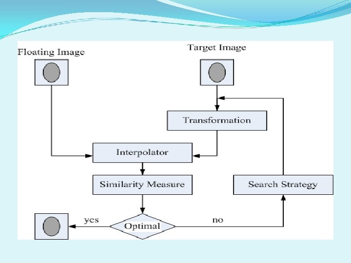
CUDA Algorithm for NMI registration The registration procedure spent 90 -95% of its run-time on mutual information computation. Medical image registration has a high level of data parallelism and image data can be mapped onto the GPUs platform. Based on our normalized mutual information method, the tasks are classified into four CUDA kernels as follows: Transformation – This group performs coordinate transform, affine transform, and mapping matrix to establish spatial correspondence between two images. Interpolation – This group involves iteratively transforming image A with respect to image B while optimizing the MI measure which is calculated from corresponding voxel values. Histogram – This group computes a joint histogram of the pairs of images to evaluate the mutual information. Optimization – This group detects optimization of estimate transformation to evaluate its similarity
The CUDA implementation consists of four stages: 1) Allocate data memory on the device and transfer them from the host to the device. 2) Set up the function kernel configuration. 3) Launch function kernel(s) and store the result in the device memory. 4) Transfer data from the device memory to the host memory.
CUDA Implementation Experimental Results The experiments involved the data sets of 7 patients, each consisting of Computed Tomography (CT) and six Magnetic-Resonance (MR) volumes. On a PC, having a 2. 40 GHz Intel® Core™ 2 Quad CPUs, and 4 GB DDR 2 memory with NVIDIA’s Ge. Force 9600 GT graphic card. All CT images were registered to the MR images using the MR image as the reference image on PC Run the registration procedure on both for the CPU-base platform (C program), and the GPUs platform (the CUDA program). Experimental results showed that the GPU implementation improves the registration computational performance with a speedup factor of 23. 4×
Comparison of GPU and CPU-based implementation for the registration procedure runtimes Run Time Range for 41 pairs data set on CPU and GPU Run Time Average (mins. ) CPU-based 7. 41 ~ 18. 34 12. 20 1 GPU-based 0. 33 ~ 0. 633 0. 5 23. 4 Architecture Speedup