FD CD A v CD coefficient of drag


 always -------- to direction of the")

 and C of G")


 ØThe point on a projectile where the both the Lift")


 Back Spin")
")


- Slides: 21
FD = ½ CD A ρ v² • CD coefficient of drag, indicates how streamlined a projectile is (low number: very streamlined) • A is the frontal area of projectile facing the flow • ρ (rho) is the air density (less in warm air and at higher altitude) • v² means if v doubles, drag quadruples
TERMINAL VELOCITY Ø Vterminal reached when all Fresistive = all Fmotive Ø as a body falls, it accelerates drag Ø drag as the square of v (v = 4, drag = 16) Ø Vterminal can also be reached horizontally Ø light body reaches Vterminal ----than heavier Ø badminton bird compared with
STREAMLINING • Achieved by: 1. decreasing area size facing oncoming airflow 2. tapering leading side air not abruptly moved • Effects of Streamlining: A. more laminar flow past body with less “wake” B. less turbulence behind body less difference in pressure zones between front and tail of body
DRAFTING ü For given body & wind v, Headwind has a greater effect than Tailwind on the moving body: (run @ 6 mps with 2 mps wind: H = 8 mps, T = 4 mps) ü Running @ 1 meter behind = ----% energy saved ü XC Skiing @ 1 meter behind = ----% energy saved ü 90% of all resistive forces in Cycling are DRAG
FLUID LIFT FORCE on AIRFOILS ØFL (Lift Force) always -------- to direction of the oncoming air flow Ø Lift can be ---------, -------Ø due to difference in pressure zones on opposite sides of projectile Ø Bernoulli’s Principle: flow v = pressure zone / flow v = p zone ØFL affected by Projection and Attack
Angles Affecting LIFT ØPROJECTION ØATTITUDE ØATTACK
Angles Affecting LIFT PROJECTION angle between horizontal (e. g. ground) and C of G of projectile FIG 13. 5 on page 436
Projecti on
Angles Affecting LIFT ATTITUDE angle between horizontal and long axis of projectile FIG 13. 6 on page 437
Discus descending to ground from left to right Projection 45° Attitude 30°
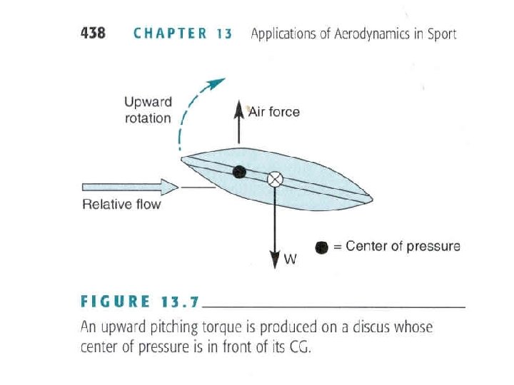
Angles Affecting LIFT ATTACK angle between projectile’s long axis and projection FIG K. 9 on page 424 FIG 13. 8 on page 438
Attack below from page 424 Above FIG 13. 8 at apex of flight page 438
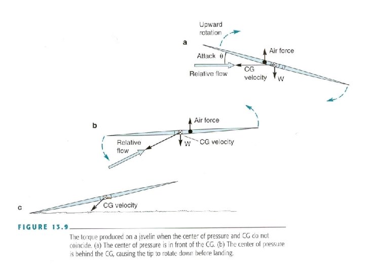
Center of Pressure (CP) ØThe point on a projectile where the both the Lift and Drag Forces act Øchanges as the Attack changes Ø CG and CP co-linear = LIFT Ø CG and CP out of line = Torque pitch Drag Ø CP in front of CG = Stall leading side pitch up Ø see FIG 13. 9 on page 439
MAGNUS EFFECT Ø Lift due to the spin on a spherical projectile Ø Projectile has a Boundary layer of air that moves in the direction of the spin Ø Projectile’s Boundary layer of air interfaces with on coming air flow Ø High and Low pressure zones develop due to difference in air flow velocities [Bernoulli]
Back Spin ü Bottom of ball moving toward the direction of the ball’s flight ü higher flow on top = pressure ü lower flow on bottom = pressure ü lift UPWARD Top Spin ü Top of the ball moving toward the direction of the ball’s flight ü lower flow on top = pressure ü higher flow on bottom = pressure ü lift DOWNWARD
Back Spin (top of ball moves backwards, away from ball’s flight path) Back Spin produces upward Lift Force
Top Spin (top of ball moves forward in the direction of ball’s flight path) Top Spin produces downward Lift Force
“Basic Biomechanics” Susan J. Hall page 531
Floater Serve / Knuckleball Pitch • all sport balls are not perfectly round in shape • when a ball is projected with little or no spin: 1. the shape causes irregular/shifting air flow past the various sides of the ball 2. high and low pressure zones continually shift around the ball