elink IP for FE ASICs VFAT 3Gd SP

- Slides: 12
e-link IP for FE ASICs VFAT 3/Gd. SP ASIC design meeting 19/07/2011
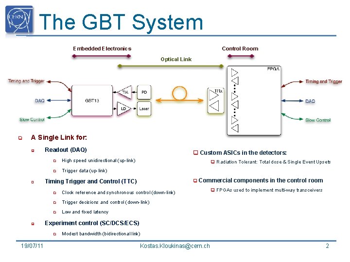
The GBT System Embedded Electronics Control Room Optical Link q A Single Link for: q q q Readout (DAQ) q High speed unidirectional (up-link) q Trigger data (up-link) q Radiation Tolerant: Total dose & Single Event Upsets q Commercial components in the control room Timing Trigger and Control (TTC) q Clock reference and synchronous control (down-link) q Trigger decisions and control (down-link) q Low and fixed latency q FPGAs used to implement multi-way transceivers Experiment control (SC/DCS/ECS) q 19/07/11 q Custom ASICs in the detectors: Modest bandwidth (bidirectional link) Kostas. Kloukinas@cern. ch 2
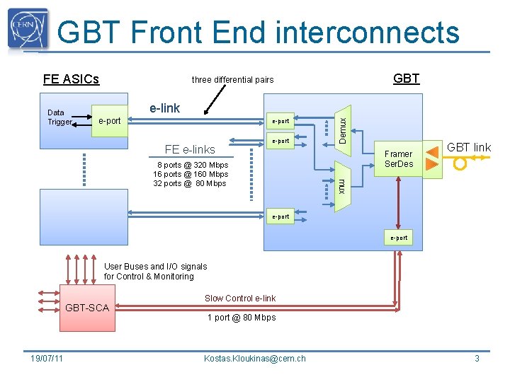
GBT Front End interconnects FE ASICs e-link e-port FE e-links e-port Demux Data Trigger GBT three differential pairs Framer Ser. Des mux 8 ports @ 320 Mbps 16 ports @ 160 Mbps 32 ports @ 80 Mbps GBT link e-port User Buses and I/O signals for Control & Monitoring GBT-SCA 19/07/11 Slow Control e-link 1 port @ 80 Mbps Kostas. Kloukinas@cern. ch 3
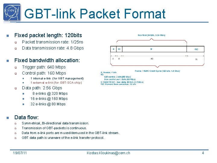
GBT-link Packet Format n Fixed packet length: 120 bits q q n Packet transmission rate: 1/25 ns Data transmission rate: 4. 8 Gbps Fixed bandwidth allocation: q q Trigger path: 640 Mbps Control path: 160 Mbps n n q Data path: 2. 56 Gbps n n 1 internal e-link (for GBT management) 1 external e-link (for GBT-SCA chip) 8 e-links @ 320 Mbps 16 e-links @ 160 Mbps 32 e-links @ 80 Mbps Data flow: q q Symmetrical, Bi-directional data transmission. Transmission of GBT-packets is continuous. Data from e-link ports are muxed/demuxed in the GBT-link stream. GBT data path is unaware of the e-link transfer protocol. 19/07/11 Kostas. Kloukinas@cern. ch 4
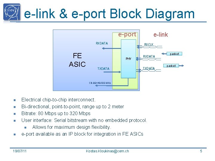
e-link & e-port Block Diagram e-port RXDATA FE ASIC e-link RXCLK PHY TXDATA RXDATA TXDATA packet Clk 80/160/320 MHz n n n Electrical chip-to-chip interconnect. Bi-directional, point-to-point, range up to 2 meter Bitrate: 80 Mbps up to 320 Mbps User interface: Serial bitstream with no embedded protocol. n Allows for maximum design flexibility. e-port available as an IP block for integration in FE ASICs 19/07/11 Kostas. Kloukinas@cern. ch 5
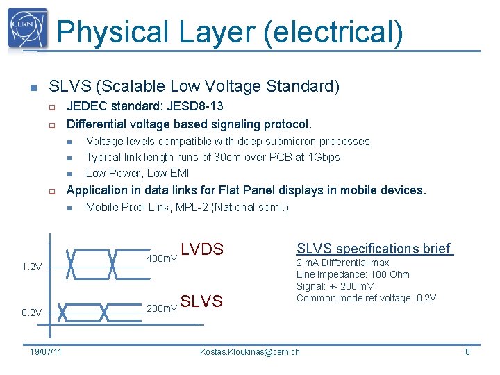
Physical Layer (electrical) n SLVS (Scalable Low Voltage Standard) q q JEDEC standard: JESD 8 -13 Differential voltage based signaling protocol. n n n q Application in data links for Flat Panel displays in mobile devices. n 1. 2 V 0. 2 V 19/07/11 Voltage levels compatible with deep submicron processes. Typical link length runs of 30 cm over PCB at 1 Gbps. Low Power, Low EMI Mobile Pixel Link, MPL-2 (National semi. ) 400 m. V 200 m. V LVDS SLVS specifications brief 2 m. A Differential max Line impedance: 100 Ohm Signal: +- 200 m. V Common mode ref voltage: 0. 2 V Kostas. Kloukinas@cern. ch 6
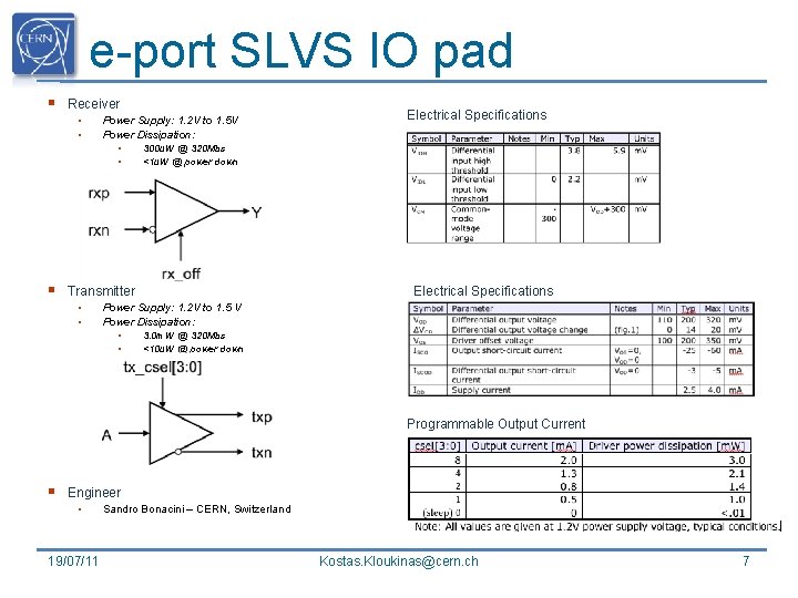
e-port SLVS IO pad § Receiver • • Power Supply: 1. 2 V to 1. 5 V Power Dissipation: • • § 300 u. W @ 320 Mbs <1 u. W @ power down Electrical Specifications Transmitter • • Electrical Specifications Power Supply: 1. 2 V to 1. 5 V Power Dissipation: • • 3. 0 m. W @ 320 Mbs <10 u. W @ power down Programmable Output Current § Engineer • 19/07/11 Sandro Bonacini – CERN, Switzerland Kostas. Kloukinas@cern. ch 7
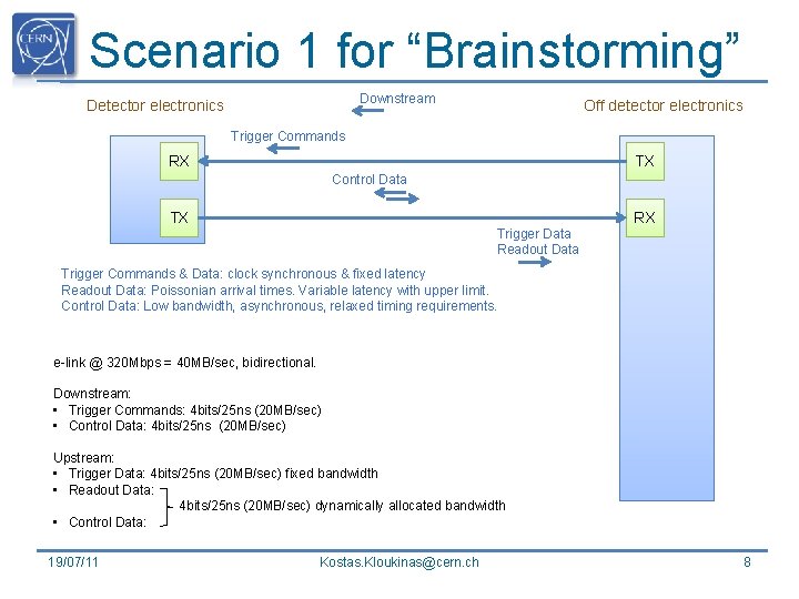
Scenario 1 for “Brainstorming” Downstream Detector electronics Off detector electronics Trigger Commands RX TX Control Data TX Trigger Data Readout Data RX Trigger Commands & Data: clock synchronous & fixed latency Readout Data: Poissonian arrival times. Variable latency with upper limit. Control Data: Low bandwidth, asynchronous, relaxed timing requirements. e-link @ 320 Mbps = 40 MB/sec, bidirectional. Downstream: • Trigger Commands: 4 bits/25 ns (20 MB/sec) • Control Data: 4 bits/25 ns (20 MB/sec) Upstream: • Trigger Data: 4 bits/25 ns (20 MB/sec) fixed bandwidth • Readout Data: 4 bits/25 ns (20 MB/sec) dynamically allocated bandwidth • Control Data: 19/07/11 Kostas. Kloukinas@cern. ch 8
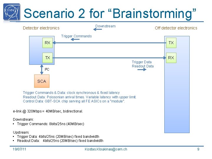
Scenario 2 for “Brainstorming” Downstream Detector electronics Off detector electronics Trigger Commands RX TX TX Trigger Data Readout Data I 2 C RX SCA Trigger Commands & Data: clock synchronous & fixed latency Readout Data: Poissonian arrival times. Variable latency with upper limit. Control Data: GBT-SCA chip serving all FE ASICs on a “module”. e-link @ 320 Mbps = 40 MB/sec, bidirectional. Downstream: • Trigger Commands: 8 bits/25 ns (40 MB/sec) Upstream: • Trigger Data: 4 bits/25 ns (20 MB/sec) fixed bandwidth • Readout Data: 4 bits/25 ns (20 MB/sec) fixed bandwidth 19/07/11 Kostas. Kloukinas@cern. ch 9
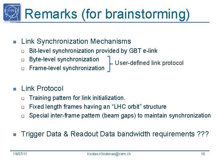
Remarks (for brainstorming) n Link Synchronization Mechanisms q q q n Link Protocol q q q n Bit-level synchronization provided by GBT e-link Byte-level synchronization User-defined link protocol Frame-level synchronization Training pattern for link initialization. Fixed length frames having an “LHC orbit” structure Special inter-frame pattern (beam gaps) to maintain synchronization Trigger Data & Readout Data bandwidth requirements ? ? ? 19/07/11 Kostas. Kloukinas@cern. ch 10
THANK YOU 19/07/11 Kostas. Kloukinas@cern. ch 11
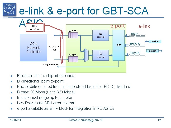
e-link & e-port for GBT-SCA ASIC e-port e-link FIFO Interface SCA Network Controller RX FIFO RX control RXCLK PHY ATLANTIC Bus TX FIFO TX control RXDATA TXDATA packet Clk @ 40/80 MHz n n n n Electrical chip-to-chip interconnect. Bi-directional, point-to-point. Packet data oriented transaction protocol based on HDLC standard. Bitrate: 80 Mbps (up to 320 Mbps). Interconnect range up to 2 meter. Low Power and SEU error tolerant. e-port available as an IP block for integration in FE ASICs 19/07/11 Kostas. Kloukinas@cern. ch 12