RadHard ASICS for Optical Data Transmission K K

- Slides: 21
Rad-Hard ASICS for Optical Data Transmission K. K. Gan, H. P. Kagan, R. D. Kass, H. Merritt, J. Moore, A. Nagarkar, D. Pignotti, S. Smith, M. Strang The Ohio State University P. Buchholz, A. Wiese, M. Ziolkowski Universität Siegen OUTLINE Introduction Result on 4 -channel Driver/Receiver with Redundancy Design of new 12 -channel Driver/Receiver with Redundancy Summary/Conclusions R. Kass DPF 2011 1
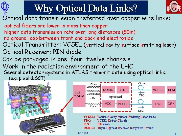
Why Optical Data Links? Optical data transmission preferred over copper wire links: optical fibers are lower in mass than copper higher data transmission rate over long distances (80 m) no ground loop between front and back end electronics Optical Transmitter: VCSEL (vertical cavity surface-emitting laser) Optical Receiver: PIN diode Can be packaged in one, four, twelve channels Work in the radiation environment of the LHC Several detector systems in ATLAS transmit data using optical links. (e. g. pixel & SCT) ~80 m ~1 m R. Kass ~1. 85 m VCSEL: VDC: PIN: DORIC: DPF 2011 optoboard Vertical Cavity Surface Emitting Laser diode VCSEL Driver Circuit Pi. N diode Digital Optical Receiver Integrated Circuit 2
Array Optical Links Array solution has several major advantages over a single fiber system: compact: more channels in less space robust: 12 -fiber ribbon stronger than individual fiber efficient: can reserve 1 in 12 channels for redundancy instead of doubling the number of fibers for a single fiber system VCSEL/PIN array based links are commercially available: 12 -fiber ribbon, 12 channel VCSEL/PIN array, 10 Gb/s each Þ 120 GB/s ! 12 -channel VCSEL & PIN arrays available from several vendors Vendors provide reliability and qualification info. Situation better than in 2003 when implementing array based on-detector links for ATLAS pixel detector: We only had to fabricate 272 array-based opto-boards for 1744 pixel modules. R. Kass DPF 2011 3
Driver/Receiver with Redundancy We designed an updated version of the VCSEL driver and PIN receiver used in the current ATLAS pixel detector. Þ Added redundancy Possible applications include current ATLAS pixel detector and its upgrade IBL (insertable B-Layer) in 2013 -14 Experience gained from the development/testing of new chips could help the development of on-detector array-based opto-links for high luminosity up grades to the LHC Submitted 1 st prototype chip in Feb. 2010 process: 130 nm CMOS R. Kass DPF 2011 4
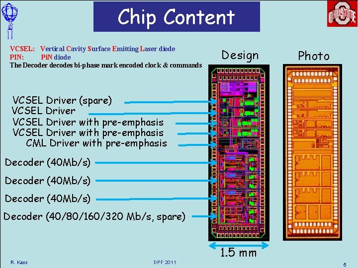
Chip Content VCSEL: Vertical Cavity Surface Emitting Laser diode PIN: Pi. N diode The Decoder decodes bi-phase mark encoded clock & commands Design Photo VCSEL Driver (spare) VCSEL Driver with pre-emphasis CML Driver with pre-emphasis Decoder (40 Mb/s) Decoder (40/80/160/320 Mb/s, spare) R. Kass DPF 2011 1. 5 mm 5
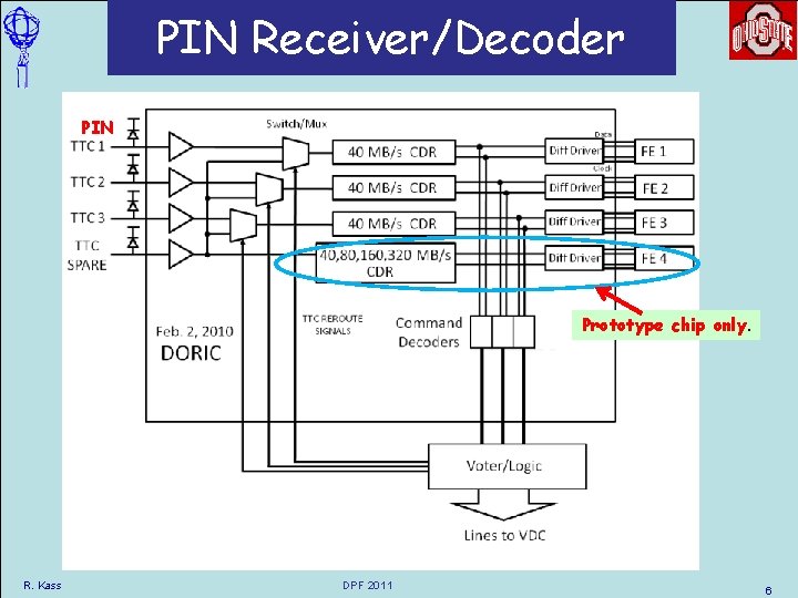
PIN Receiver/Decoder PIN Prototype chip only. R. Kass DPF 2011 6
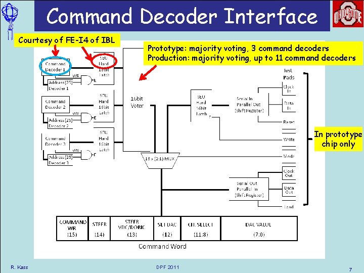
Command Decoder Interface Courtesy of FE-I 4 of IBL Prototype: majority voting, 3 command decoders Production: majority voting, up to 11 command decoders In prototype chip only R. Kass DPF 2011 7
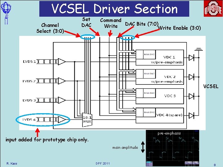
VCSEL Driver Section Channel Select (3: 0) Set DAC Command Write DAC Bits (7: 0)Write Enable (3: 0) VCSEL pre-emphasis input added for prototype chip only. main amplitude R. Kass DPF 2011 8
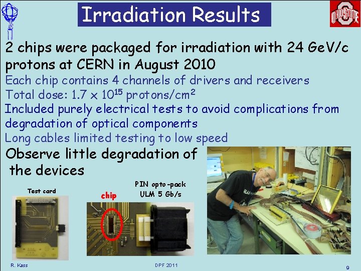
Irradiation Results 2 chips were packaged for irradiation with 24 Ge. V/c protons at CERN in August 2010 Each chip contains 4 channels of drivers and receivers Total dose: 1. 7 x 10¹⁵ protons/cm 2 Included purely electrical tests to avoid complications from degradation of optical components Long cables limited testing to low speed Observe little degradation of the devices Test card R. Kass chip PIN opto-pack ULM 5 Gb/s DPF 2011 9
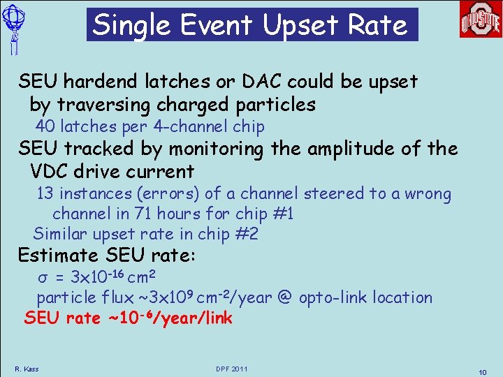
Single Event Upset Rate SEU hardend latches or DAC could be upset by traversing charged particles 40 latches per 4 -channel chip SEU tracked by monitoring the amplitude of the VDC drive current 13 instances (errors) of a channel steered to a wrong channel in 71 hours for chip #1 Similar upset rate in chip #2 Estimate SEU rate: σ = 3 x 10 -16 cm 2 particle flux ~3 x 109 cm-2/year @ opto-link location SEU rate ~10 -6/year/link R. Kass DPF 2011 10
Summary 0 f 2010 Prototype Chip Prototyped 4 -channel VCSEL driver & PIN receiver/decoder: Incorporated experience from current opto-links by adding: redundancy to bypass broken PIN or VCSEL channel individual VCSEL current control power-on reset to set VCSEL current to ~ 10 m. A on power up Results of tests: VCSEL driver can operate up to ~ 5 Gb/s with BER < 5 x 10 -13 PIN receiver/decoder works even at low threshold Irradiation with 24 Ge. V protons to 1. 7 x 10¹⁵ p/cm 2 Very low SEU rate in latches ~3 x 10 -7/year/link small decrease in VCSEL driver output current R. Kass DPF 2011 11
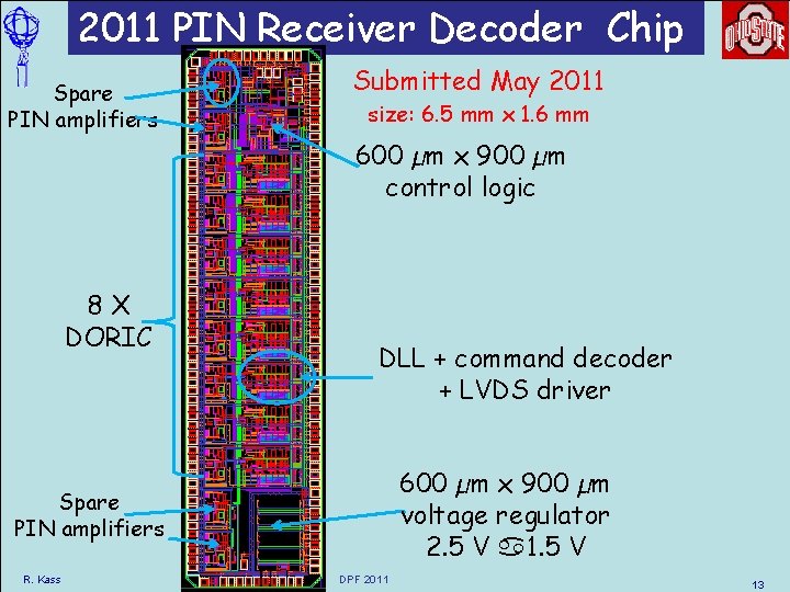
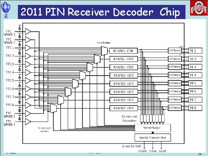
2011 PIN Receiver Decoder Chip Decodes 40 Mb/s bi-phase mark (BPM) signal 4 spare PIN receivers for redundancy 8 FE-I 4 command decoders Allows remote control by voting between commands received by the 8 FE-I 4 command decoders If one of the 8 inner PIN diodes fail a signal from one of the 4 redundant channel amplifier outputs can be steered to the digital portion of the failed channel Majority voting of the command decoder values determines the command to be executed Allows working control if only 2 PIN channels are alive R. Kass DPF 2011 12
2011 PIN Receiver Decoder Chip Spare PIN amplifiers Submitted May 2011 size: 6. 5 mm x 1. 6 mm 600 µm x 900 µm control logic 8 X DORIC DLL + command decoder + LVDS driver 600 µm x 900 µm voltage regulator 2. 5 V a 1. 5 V Spare PIN amplifiers R. Kass DPF 2011 13
2011 PIN Receiver Decoder Chip K. K. Gan R. Kass RD 11 DPF 2011 14 14
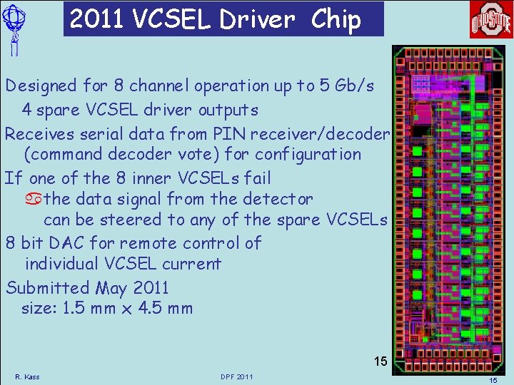
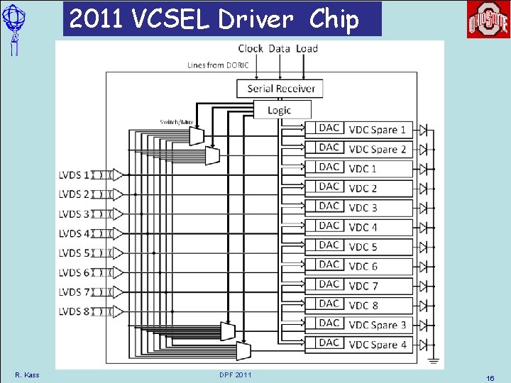
2011 VCSEL Driver Chip Designed for 8 channel operation up to 5 Gb/s 4 spare VCSEL driver outputs Receives serial data from PIN receiver/decoder (command decoder vote) for configuration If one of the 8 inner VCSELs fail athe data signal from the detector can be steered to any of the spare VCSELs 8 bit DAC for remote control of individual VCSEL current Submitted May 2011 size: 1. 5 mm x 4. 5 mm 15 R. Kass DPF 2011 15
2011 VCSEL Driver Chip R. Kass DPF 2011 16
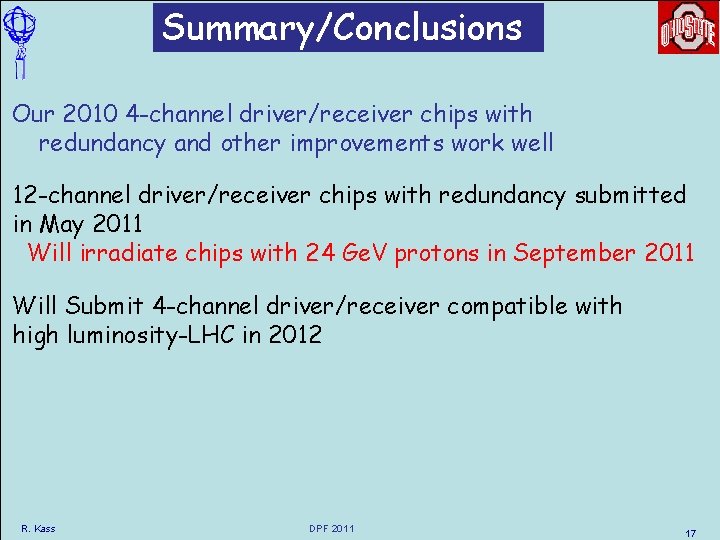
Summary/Conclusions Our 2010 4 -channel driver/receiver chips with redundancy and other improvements work well 12 -channel driver/receiver chips with redundancy submitted in May 2011 Will irradiate chips with 24 Ge. V protons in September 2011 Will Submit 4 -channel driver/receiver compatible with high luminosity-LHC in 2012 R. Kass DPF 2011 17
Extra Slides R. Kass DPF 2011 18
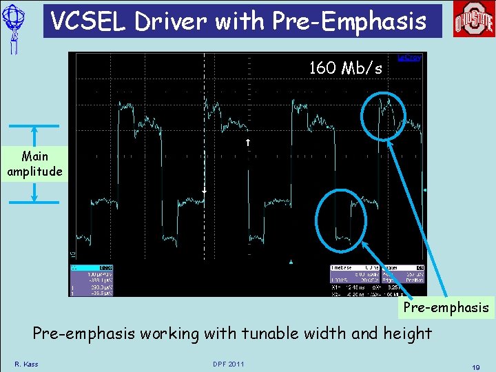
VCSEL Driver with Pre-Emphasis 160 Mb/s Main amplitude Pre-emphasis working with tunable width and height R. Kass DPF 2011 19
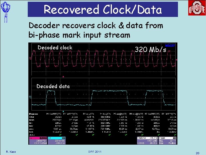
Recovered Clock/Data Decoder recovers clock & data from bi-phase mark input stream Decoded clock 320 Mb/s Decoded data R. Kass DPF 2011 20
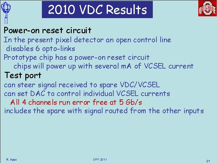
2010 VDC Results Power-on reset circuit In the present pixel detector an open control line disables 6 opto-links Prototype chip has a power-on reset circuit chips will power up with several m. A of VCSEL current Test port can steer signal received to spare VDC/VCSEL can set DAC to control individual VCSEL currents All 4 channels run error free at 5 Gb/s includes the spare with signal routed from the other inputs R. Kass DPF 2011 21