ECE 3317 Applied Electromagnetic Waves Prof David R

- Slides: 24
ECE 3317 Applied Electromagnetic Waves Prof. David R. Jackson Fall 2020 Notes 16 Plane Waves in Good Conductors 1
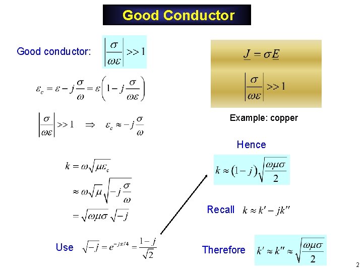
Good Conductor Good conductor: Example: copper Hence Recall Use Therefore 2
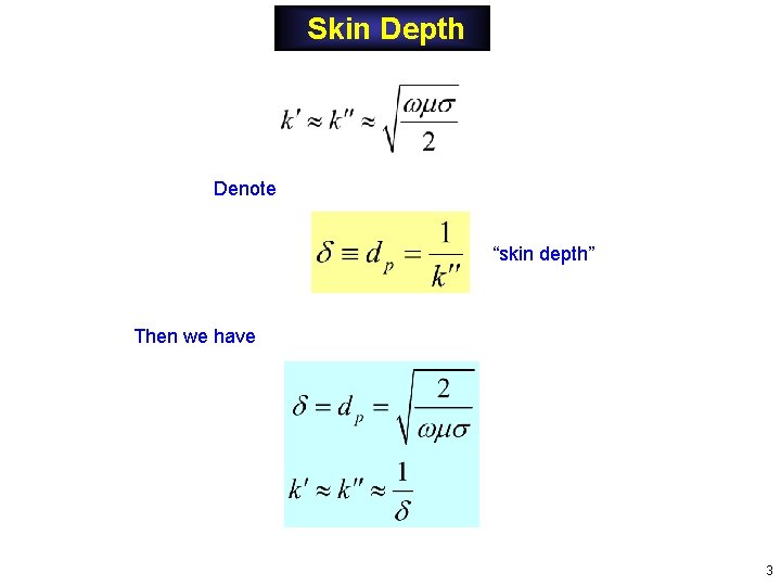
Skin Depth Denote “skin depth” Then we have 3
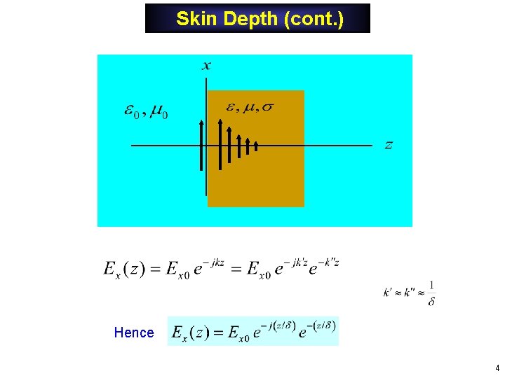
Skin Depth (cont. ) Hence 4
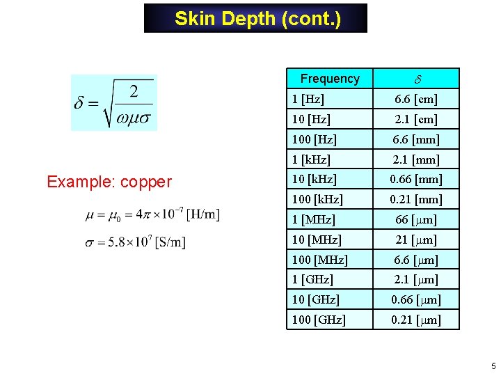
Skin Depth (cont. ) Frequency Example: copper 1 [Hz] 6. 6 [cm] 10 [Hz] 2. 1 [cm] 100 [Hz] 6. 6 [mm] 1 [k. Hz] 2. 1 [mm] 10 [k. Hz] 0. 66 [mm] 100 [k. Hz] 0. 21 [mm] 1 [MHz] 66 [ m] 10 [MHz] 21 [ m] 100 [MHz] 6. 6 [ m] 1 [GHz] 2. 1 [ m] 10 [GHz] 0. 66 [ m] 100 [GHz] 0. 21 [ m] 5
Skin Depth (cont. ) The same penetration principle holds for curved conductors, as long as the radius of curvature is large compared with the skin depth. The distance z is measured from the boundary of the conductor. Coax Penetration into inner conductor Penetration into outer conductor 6
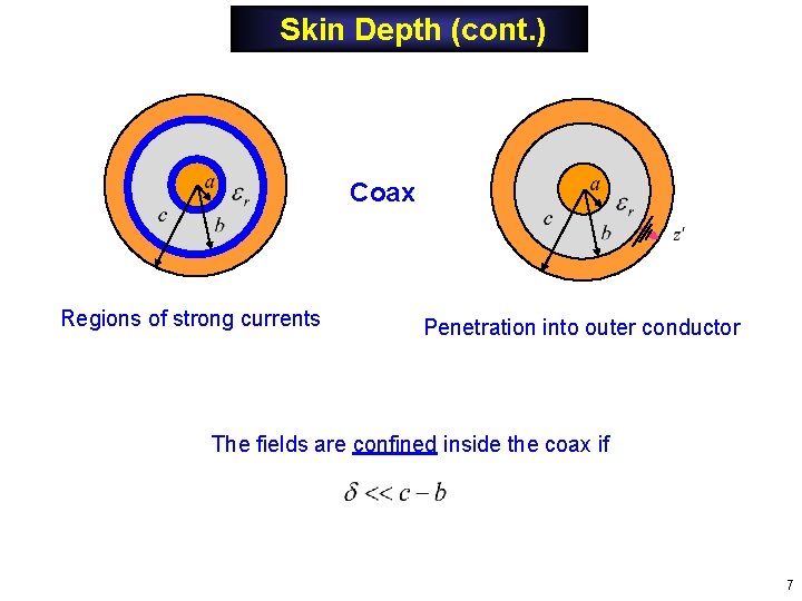
Skin Depth (cont. ) Coax Regions of strong currents Penetration into outer conductor The fields are confined inside the coax if 7
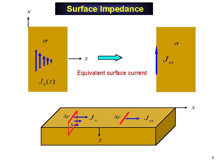
Surface Impedance Equivalent surface current 8
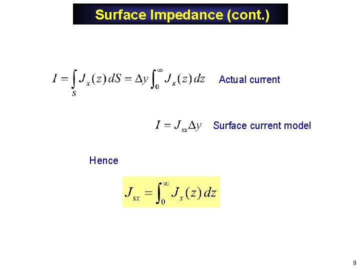
Surface Impedance (cont. ) Actual current Surface current model Hence 9
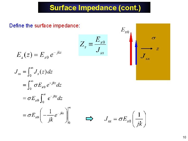
Surface Impedance (cont. ) Define the surface impedance: 10
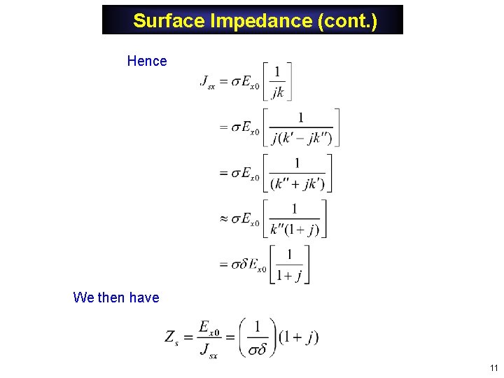
Surface Impedance (cont. ) Hence We then have 11
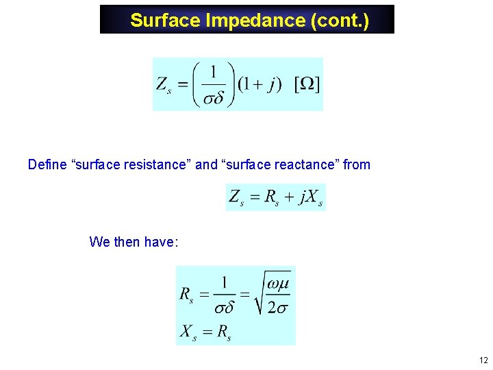
Surface Impedance (cont. ) Define “surface resistance” and “surface reactance” from We then have: 12
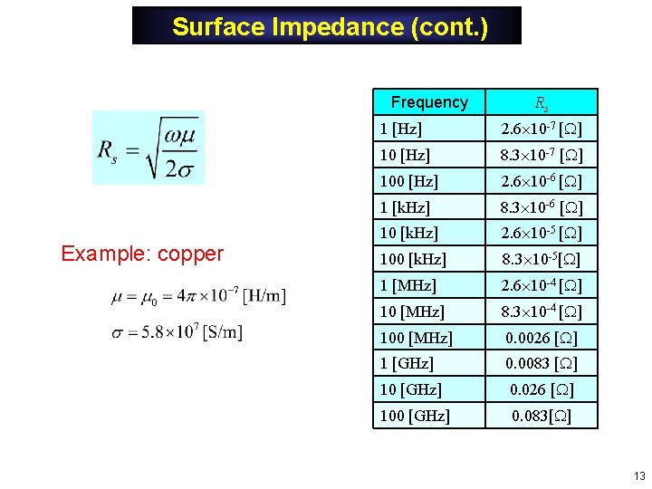
Surface Impedance (cont. ) Frequency Example: copper Rs 1 [Hz] 2. 6 10 -7 [ ] 10 [Hz] 8. 3 10 -7 [ ] 100 [Hz] 2. 6 10 -6 [ ] 1 [k. Hz] 8. 3 10 -6 [ ] 10 [k. Hz] 2. 6 10 -5 [ ] 100 [k. Hz] 8. 3 10 -5[ ] 1 [MHz] 2. 6 10 -4 [ ] 10 [MHz] 8. 3 10 -4 [ ] 100 [MHz] 0. 0026 [ ] 1 [GHz] 0. 0083 [ ] 10 [GHz] 0. 026 [ ] 100 [GHz] 0. 083[ ] 13
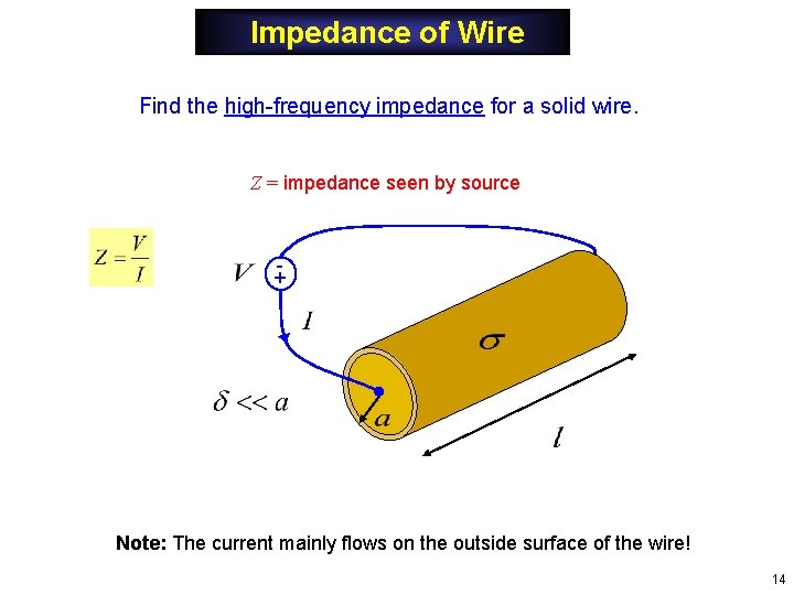
Impedance of Wire Find the high-frequency impedance for a solid wire. Z = impedance seen by source + Note: The current mainly flows on the outside surface of the wire! 14
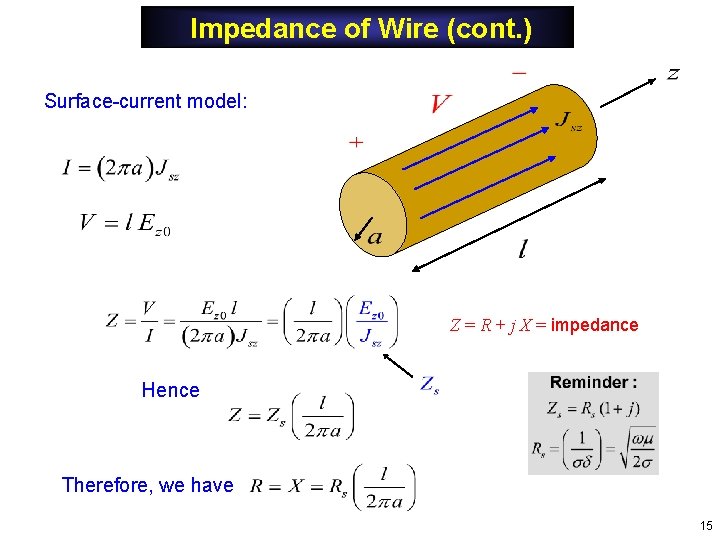
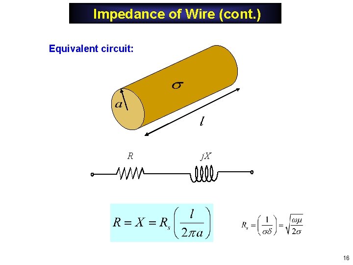
Impedance of Wire (cont. ) Surface-current model: Z = R + j X = impedance Hence Therefore, we have 15
Impedance of Wire (cont. ) Equivalent circuit: R j. X 16
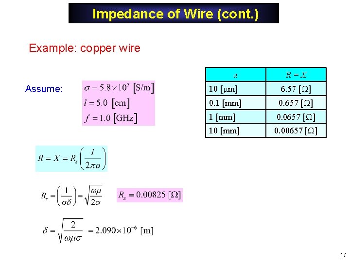
Impedance of Wire (cont. ) Example: copper wire a Assume: R=X 10 [ m] 6. 57 [ ] 0. 1 [mm] 0. 657 [ ] 1 [mm] 0. 0657 [ ] 10 [mm] 0. 00657 [ ] 17
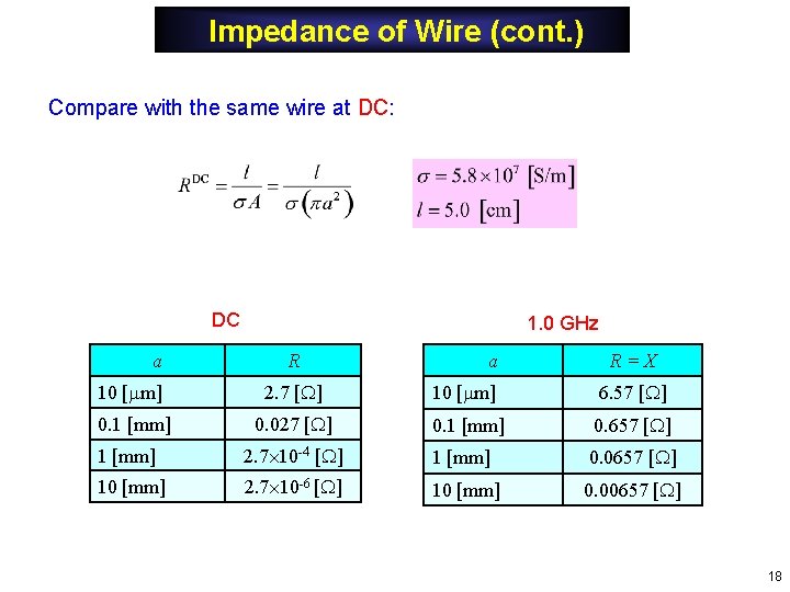
Impedance of Wire (cont. ) Compare with the same wire at DC: DC a 1. 0 GHz R a R=X 10 [ m] 2. 7 [ ] 10 [ m] 6. 57 [ ] 0. 1 [mm] 0. 027 [ ] 0. 1 [mm] 0. 657 [ ] 1 [mm] 2. 7 10 -4 [ ] 1 [mm] 0. 0657 [ ] 10 [mm] 2. 7 10 -6 [ ] 10 [mm] 0. 00657 [ ] 18
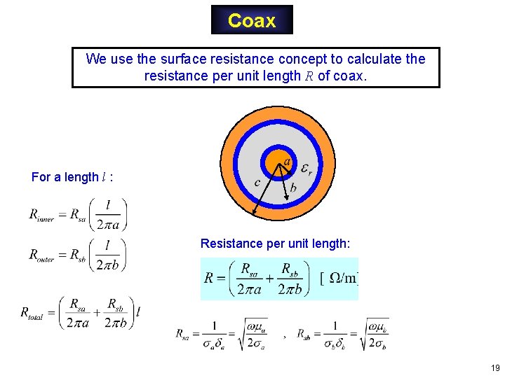
Coax We use the surface resistance concept to calculate the resistance per unit length R of coax. For a length l : Resistance per unit length: 19
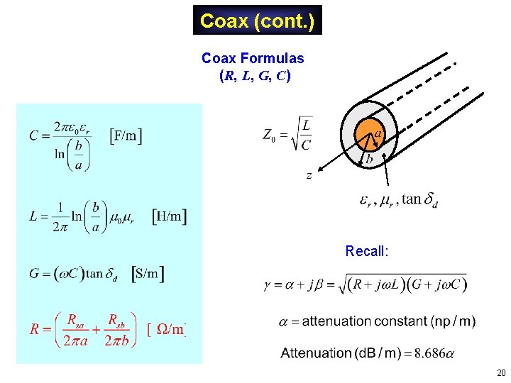
Coax (cont. ) Coax Formulas (R, L, G, C) Recall: 20
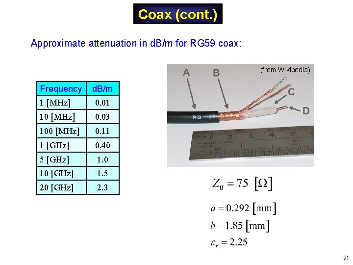
Coax (cont. ) Approximate attenuation in d. B/m for RG 59 coax: (from Wikipedia) Frequency d. B/m 1 [MHz] 0. 01 10 [MHz] 0. 03 100 [MHz] 0. 11 1 [GHz] 0. 40 5 [GHz] 1. 0 10 [GHz] 1. 5 20 [GHz] 2. 3 21
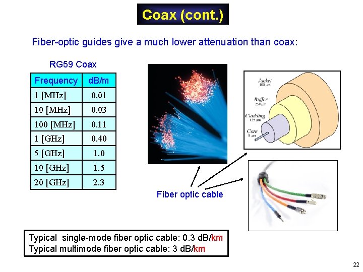
Coax (cont. ) Fiber-optic guides give a much lower attenuation than coax: RG 59 Coax Frequency d. B/m 1 [MHz] 0. 01 10 [MHz] 0. 03 100 [MHz] 0. 11 1 [GHz] 0. 40 5 [GHz] 1. 0 10 [GHz] 1. 5 20 [GHz] 2. 3 Fiber optic cable Typical single-mode fiber optic cable: 0. 3 d. B/km Typical multimode fiber optic cable: 3 d. B/km 22
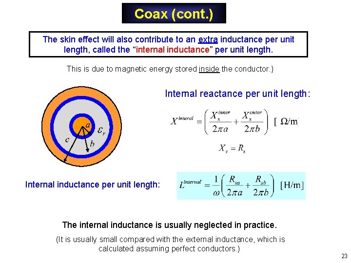
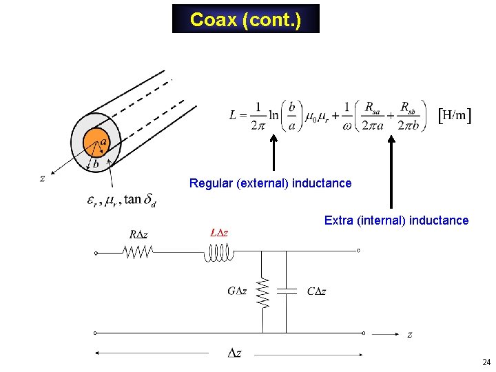
Coax (cont. ) The skin effect will also contribute to an extra inductance per unit length, called the “internal inductance” per unit length. This is due to magnetic energy stored inside the conductor. ) Internal reactance per unit length: Internal inductance per unit length: The internal inductance is usually neglected in practice. (It is usually small compared with the external inductance, which is calculated assuming perfect conductors. ) 23
Coax (cont. ) Regular (external) inductance Extra (internal) inductance 24