Design of Staircases Introduction Reinforced concrete RC stairs


- Slides: 40

Design of Staircases

Introduction üReinforced concrete (RC) stairs are an important component of a building and often the only means of providing access between the various floors of a building. üThe staircase essentially consists of landings and flights. Often, the flight is an inclined slab consisting of risers and treads (collectively called the going of staircase), whereas the landing is a horizontal slab (see Fig. 17. 1). üFrom a structural point of view, a staircase consists of slab or beam elements.

Fig. 17. 1 Components of a staircase (a) Plan of staircase (b) Terminology used (c) Part section

Definition of Terms üTread or going of step: Tread is the horizontal upper portion of a step where the foot rests. Going of step is the horizontal distance of the tread minus the nosing. üNosing: Sometimes, the tread is projected outwards for aesthetics or to provide more space; this projection is called the nosing. Many times, the nosing is provided by the finishing over the concrete tread (see Fig. 17. 1 c). üRiser and rise: Rise is the vertical distance between two consecutive treads and riser is the vertical portion of the step.

Definition of Terms üFlight or going of stair: Flight is a series of steps provided between two landings. Going of stair is the horizontal projection of the flight. üLanding: Landing is the horizontal slab provided between two flights. It is provided every 10– 14 steps for comfort in climbing. Landing is also provided when there is a change in the direction of the stairs. üOverlap: The amount by which the nosing of a tread (or landing) over sails the next lower tread (or landing) is called the overlap. üWaist: It is the least thickness of a stair slab.

Definition of Terms üWinder: The radiating or angular tapering step is called winder. üSoffit: It is the bottom surface of a stair slab. üHeadroom: The vertical distance of a line connecting the nosings of all treads and the soffit is referred to as the headroom. üSteps may be of three types as follows (see Fig. 17. 2): (a) Brick or concrete steps on inclined slab (b) Tread-riser steps (c) Isolated steps

Fig. 17. 2 Type of steps (a) Steps on waist slab (b) Slabless tread-riser (c) Isolated steps

Types of Staircases Some of the most common geometrical configurations are shown in Fig. 17. 3, which include the following: 1. Straight flight stairs with or without intermediate landing (Figs 17. 3 a and b) 2. Quarter-turn stairs (Fig. 17. 3 c) 3. Half-turn stairs, also referred to as dog-legged or scissor-type stairs (Fig. 17. 3 d) 4. Branching stairs (Fig. 17. 3 e) 5. Open-well stairs (half-turn) (Fig. 17. 3 f) and quarter-turn landing (Fig. 17. 3 g) 6. Spiral stairs (Figs 17. 3 h and i) 7. Helicoidal stairs (Fig. 17. 3 j)

Types of Staircases Fig. 17. 3 Plan views of various types of stairs (a) and (b) Straight flight stairs (c) Quarter-turn stairs (d) Half-turn stairs (e) Branching stairs (f) Open-well (half-turn) stairs (g) Open-well stairs with quarter-turn landing (h) Part-circular stairs (i) Spiral stairs (j) Helicoidal stairs

Types of Staircases üSpiral, helical, circular, and elliptical stairs are also referred to as geometrical stairs. üThe type of stair and its location are selected based on architectural considerations, such as accessibility, function, comfort, lighting, ventilation, and aesthetics, as well as structural and economic considerations. üFree-standing stairs, which are similar to dog-legged stairs in plan, but with their landing unsupported, provide an elegant appearance. They are three-dimensional structures and have to be fixed at both the top and bottom ends for stability, as shown in Fig. 17. 4.

Free-standing Stair Fig. 17. 4 Typical free-standing stair (a) Plan (b) Section (c) Isometric view

Free-Standing Stair at Marlins Ball. Park, Miami, Florida

Structural Classifications For design purposes, stairs are classified into the following two types, depending on the predominant direction in which the slab of the stair deflects in flexure: 1. Transversely supported (transverse to the direction of movement in the stair) 2. Longitudinally supported (in the direction of movement)

Transversely Supported Stairs Transversely supported stairs include the following types: 1. Simply supported steps supported by two walls or beams or a combination of both (see Fig. 17. 5 a) 2. Stairs cantilevering from a central spine beam (see Fig. 17. 5 b) 3. Steps cantilevering from a wall or a beam (see Fig. 17. 5 c). The detailing of stair slab when concrete or brick step is adopted is also shown in Fig. 17. 5(d). It has to be noted that the tread-riser type of arrangement is also employed as cantilevers.

Fig. 17. 5 Transversely supported stairs (a) Supported between two stringer beams or walls (b) Doubly cantilevered from a central spine beam (c) Cantilevered from spandrel beam or wall (d) Detailing of cantilever stair for concrete and brick steps

Transversely Supported Stairs üWhen the slab is supported at the two sides by stringer beams or walls as shown in Fig. 17. 5(a), it should be designed as simply supported. The stringer beam in Fig. 17. 5(a) may also be provided as an upstand stringer. üThe spandrel beam (see Fig. 17. 5 c) is subjected to equilibrium torsion in addition to bending moment and shear. Although the slab may be spanning transversely, the spandrel and spine beams of Figs 17. 5(a) and (c), respectively, span longitudinally between the supporting columns.

Transversely Supported Stairs üWhen the slab is doubly cantilevered from the central spine beam as in Fig. 17. 5(b), it is better to check for the case of loading on one side of the stair slab, which may induce torsion in the spine beam. This condition may also dislodge the slab from the beam if proper detailing is not provided. üThe detail as shown in Fig. 17. 5(b) may prevent such a separation, as the stirrups of the beam will anchor the slab into the beam, provided the stirrups are designed to take into account torsion as well.

Longitudinally Supported Stairs üThese stairs span between the supports at the top and bottom of a flight and are unsupported at the sides. üLongitudinally supported stairs may be supported in any of the following ways: 1. Internal beams at the ends of the flight in addition to beams or walls at the outside edges of the landings (see Fig. 17. 6 a) 2. Beams or walls at the outside edges of the landings (see Fig. 17. 6 b)

Fig. 17. 6 Types of stairs spanning longitudinally (a) Support at top and bottom risers (b) Landing slab spanning in the same direction as stairs (c) Supported on the edge of landing slab

Longitudinally Supported Stairs 3. Landings that are supported by beams or walls running in the longitudinal direction (see Fig. 17. 6 c) 4. A combination of these three methods 5. Stairs with quarter landings associated with the open-well stairs üIn all these cases, we may adopt either the waist slab (Fig. 17. 2 a) or the tread-riser type (Fig. 17. 2 b). üThe slab thickness depends on the effective span, which should be calculated according to the boundary condition.

Longitudinally Supported Stairs üAll these staircases require four columns in plan. Of these, two columns should be used to support the landing beam. üStringers, treads, or complete flights and landings can be precast, depending upon the nature of the project, site, and size of the crane, as shown in Fig. 17. 7. üCare should be exercised when detailing the junctions of in situ concrete with precast units to avoid unsightly finishes.

Fig. 17. 7 Precast concrete flight, landing, or stringers (a) Precast flight (b) Precast concrete flight with landing (c) Precast stringers

Effective Span Following are the rules for calculating the effective spans, depending on the way the stair slab is supported: 1. When the stairs span longitudinally and are supported at the top and bottom by beams, as shown in Fig. 17. 6(a), the effective span is the distance between the respective centres of beams. 2. When the stairs span longitudinally with the landing slab also spanning in the same direction as the stairs, as shown in Fig. 17. 6(b), the effective span is the centre-to-centre distance (c/c) between the supporting beams or walls.

Effective Span 3. When the stairs span longitudinally and are supported by landings on top and bottom, which span in the transverse direction (perpendicular to the stairs), as shown in Fig. 17. 6(c), the effective span is to be taken as the total going of the stair plus half the width of the landing on each end or one metre, whichever is smaller. 4. In the case of stairs spanning transversely (horizontally in the transverse direction), as shown in Fig. 17. 5, the effective width of the stair is taken as the effective span.

Stair with Landing Supported on Three Sides üThe landing slab running at right angles to the direction of the flight and supported by walls or beams on three sides, as shown in Fig. 17. 8, are common in residential buildings. The Indian code does not have provisions for this case. üThere are two critical locations for the flexural design of such stairs: (a) The mid-span location for positive moment (b) The kink location, where the landing slab meets the inclined waist slab, for negative moment. üThe effective length may be taken as the going of this type of stair, as IS 456 provisions are very conservative[Ahmed, et al. (1995, 1996)]

Effective Span Fig. 17. 8 Stair with landing slab supported on three sides

Loads on Stair Slabs üThe dead load to be considered on the stairs includes the following: 1. Self-weight of stair slab (waist slab, tread-riser slab, or individual steps) 2. Self-weight of step 3. Self-weight of finish üThe imposed loads are assumed to act as uniformly distributed loads on the horizontal projection of the flight, that is, on the going of staircase, as well as on the landing.

Loads on Stair Slabs Type of Staircase Imposed Load (k. N/m 2) Service stairs for maintenance in water tanks, catwalks, etc. 1. 5 Staircase in residential buildings 3. 0 Staircase in offices and public buildings 5. 0 Staircase with isolated steps 1. 3 k. N/step* * This concentrated load should be applied at the free end of each cantilever step. Table 17. 2 Imposed load on staircases as per IS 875(Part 2): 1987

Distribution of Loads on Stairs According to Clause 33. 2 of IS 456, the following distribution of loads may be taken: 1. In the case of stairs with open wells, when a staircase takes a rightangled turn, the load on areas common to any such span (usually in landings) may be taken as 50 per cent in each direction, as shown in Fig. 17. 9(a). 2. When a longitudinally spanning flight or landing is embedded by at least 110 mm into walls, the loading may be assumed to act on a reduced width of flight, due to partial two-way action. The code permits this reduction in width as 150 mm, as shown in Fig. 17. 9(b). It also suggests increasing the effective breadth of the section by 75 mm.

Fig. 17. 9 Distribution of loading on stairs (a) Open well stairs (b) Stairs built into the walls

Design of Stair Slabs Spanning Transversely Isolated Tread Slabs üThese slabs are designed as cantilever slabs. üIt is important to anchor the top bars into the support. üIn earthquake zones, equal amount of bottom bars with adequate anchoring has to be provided to resist stress reversals. üIt is necessary to provide proper chairs for the main bars so that they remain at the top face during concreting operations.

Cantilevered Stairs

Design of Stair Slabs Spanning Transversely Slabless Stairs üIn these stairs, each tread-riser unit, consisting of the riser slab and one half of tread slab on either side, is assumed to act independently as a beam having a Z-section, as shown in Fig. 17. 10 (Next Slide). üThe main bars are placed at the top or bottom of the riser portion, depending upon whether the system is cantilevered or simply supported. üNominal distributors in the form of stirrups are provided.

Transversely Spanning Tread-riser Stair Fig. 17. 10 Transversely spanning tread-riser stair (a) Typical tread-riser arrangement (b) Tread-riser unit taken for design as Z-section (c) Detailing of tread-riser stair

Design of Stair Slabs Spanning Transversely Stairs with Waist Slab üIn this type of stair, the longitudinal axis of the flight is inclined to the horizontal, and the steps form a series of triangles on top of the waist slab. üIf the steps are also made of concrete, nominal reinforcement, in the form of stirrups, are provided in the steps to prevent the cracking of nosing. üThe main bars are provided transversely, at the top or bottom, depending upon whether the slab is cantilevered or simply supported.

Design Of Stair Slabs Spanning Longitudinally Slabless stairs üThe aesthetic appeal of tread-riser stair is lost if the slab thickness exceeds the riser, R. Hence, the effective span for these stairs is usually kept below 3. 5 m. üThe bending moments are considered to occur in the longitudinal direction in the riser as well as treads. Each tread slab is subjected to a bending moment combined with shear force, whereas the riser slab is subjected to a constant bending moment and an axial force (see Fig. 17. 11(a). üThe reinforcement detailing is shown in Fig. 17. 11(b) can resist the negative bending moment near the supports, arising out of any partial fixity. . `

Longitudinally Supported Tread-riser Stairs Fig. 17. 11 Longitudinally supported tread-riser stairs (a) Bending moment and shear force diagram (b) Detailing of reinforcement

Design Of Stair Slabs Spanning Longitudinally Stairs with Waist Slab üThe slab is designed as a simply supported slab. üThe reinforcements are placed longitudinally as shown in Figs 17. 12 and 17. 13 (Figure 17. 12 shows the detailing for stairs supported at the ends of landing and Fig. 17. 13 shows the detailing for stairs supported at the ends of flights). üDetailing of bars should be properly done at the junction of the flight and landing slab. üThe distributor bars are provided in the transverse direction, along the width of the waist slab.

Fig. 17. 12 Detailing of dog-legged stair supported at the ends of landing

Fig. 17. 13 Detailing of dog-legged stair supported at the ends of flights
 Precast concrete dog leg staircases
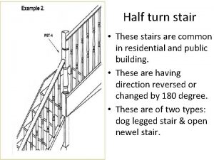
 Example of half turn stairs are
 Design compressive strength of concrete formula
 Who invented rcc
 Plastic centroid reinforced concrete
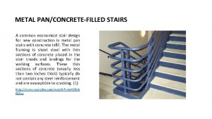
 Concrete filled metal pan stairs
 Singly reinforced beam design
 Concrete semi concrete abstract
 Concrete semi concrete abstract
 Social learning theory example
 Difference between singly and doubly reinforced beam
 Wallboard that has been reinforced with lexan®:
 Ratatosk reinforced
 Osha part 1926 subpart cc
 Reinforced composite
 Reinforced reaction injection molding
 Protruding reinforced steel must be guarded
 Scrim vci film
 Reinforced robot humor suppression pump
 Plastic state of concrete
 Introduction to concrete
 Stairs 1-4 tavlebok
 Opaque risers
 Two point perspective house
 Milli deci centi
 Hamstring stretch stairs
 Construction gcse
 Metric system stairs
 Cm dm mm
 Golden ratio in the last supper
 Every flight of stairs with four or more risers must have
 Lang stair & rail inc
 Stairs nomenclature
 Climbing stairs java
 2 point perspective stairs
 Isolated vertical load bearing member
 Kangaroos hop down mountains
 Four students run up the stairs in the time shown
 Stairs
 Brunelleschi's dome
 Donatello

