Stairs Terminology and Design Rules Why Stairs u


![Design Rules u Riser + Tread = 17” - 17 1/2” [book] (17”- 18” Design Rules u Riser + Tread = 17” - 17 1/2” [book] (17”- 18”](https://slidetodoc.com/presentation_image_h/ee771f565bed8bc603ead82c182bbd1d/image-19.jpg)


- Slides: 31

Stairs Terminology and Design Rules

Why Stairs u Important consideration in a structure – design – function u Accommodate traffic flow from one level to another u Key to circulation in a plan u Code requirements – based upon safety – established by occupant count

Stair Groupings based on Material u 3 Groupings 1 --Wood 2 --Steel 3 --Concrete

Types of Stairs u Basic types – straight run – right angle or “L” – double “L” – reverse or “U” – winder – spiral or curved

Straight Run u does not change direction u typical width is 3’-0” to 3’-6” (residential) u typical width for commercial construction is set by code u simple u popular

Right Angle or “L” u Intermediate platform between floors u A 90 degree directional change occurs, usually near the center u Platform at directional change of stairs u Platform provides a resting area between flights of stairs Platform

Double “L” u Same as “L” but with multiple platforms Platform

Reverse or U u. A 180 degree directional turn occurs, usually near center u Platform at direction change u Platform length is 2 (x) stair width Platform

Winder u Wedge shape steps u Steps continue in place of landing u Unsafe at the small of the wedge u The design: arc in the area of the winder is half the stair width and the tread design is 10” tread width

Spiral and Curved u. Spiral Stairs u Used as an additional stair--not used as the main stairs, follow code requirements u Used for unique design with requirements such as – limited or tight spaces – aesthetics – extra/addition stairs u. Curved Stairs

Stair Terminology Run/Unit Run (design run) horizontal distance from riser to riser, horizontal member Rise/Unit Rise (design rise) vertical distance between stairs/treads, vertical member Total Rise vertical distance between floors Total Run horizontal distance between first and last riser Rise Run total rise total run

Stair Terminology Landing “floor” at the bottom and top of a flight of stairs Headroom vertical distance from outside edge of step (nosing) to ceiling headroom landing stringer landing Stringer/Carriage/Stair Jack member on which risers and treads rest, provides structural support for risers and treads

Stair Terminology u Nosing – projection of tread beyond riser – usually 1 1/8” u Tread – equal to unit run + nosing u Riser – equal to unit rise

Stair Terminology u Plain Stringer – notched out 2 x 12 to support the treads and risers u Closed/Housed Stringer – stairs ends at stringer and are not exposed, stringer usually routed so the treads and risers will fit into it

Stair Terminology at a glance Run (Unit Run) Rise (Unit Rise) Total run Total rise Tread Riser Nosing Stringer (carriage) Headroom Clearance Stairwell Landing (fin fl) Kick board

Stairs Framing Terms u double header u double trimmer u stringers u joist hangers u stairwell

Design Considerations u Stairs should be comfortable to climb u 30 - 35 degree angle is optimum to prevent fatigue u Max of 16 steps between landings u Design rules have been developed with years of study and experimentation

Design Considerations u Every step should be same size u Absolute minimum ratio of riser to tread – 4” riser with 11” tread u Absolute maximum ratio of riser to tread – 7” riser with no maximum tread u Optimum ratios – 7” riser (unit rise) – 11” tread (unit run) » includes nosing
![Design Rules u Riser Tread 17 17 12 book 17 18 Design Rules u Riser + Tread = 17” - 17 1/2” [book] (17”- 18”](https://slidetodoc.com/presentation_image_h/ee771f565bed8bc603ead82c182bbd1d/image-19.jpg)
Design Rules u Riser + Tread = 17” - 17 1/2” [book] (17”- 18” usually) u 2 (x) Riser + Tread = 24” - 25” u Riser (x) Tread = 70 - 75 sq inches

Design Rule Example u Normal conditions – If: Riser = 7 and Tread = 10 7 + 10=17 (required 17 to 18) 2 x 7 + 10 = 24 (required 24 to 25) 7 x 10 = 70 (required 70 to 75) u All conditions conform to rules

Design Rule Example u. A minimum condition – If: Riser = 5 and Tread = 14 5 + 14 = 19 (required 17 to 18) 2 (x) 5 + 14 = 24 (required 24 to 25) 5 (x) 14 = 70 (required 70 to 75) �nly two rules are satisfied, okay since at least O one rule works

Stair Calculations u Necessary to determine exact riser height and total run 1. determine vertical distance between finished floors 2. divide vertical distance by approximate desired riser height to set approximate number of risers 3. round to number of whole risers 4. divide vertical distance by number of risers to get actual riser height 5. number of unit runs = number or unit rise minus 1 6. Total run: use design rule to determine unit run size then multiply by the number of unit runs

Stair Calculations Example Given: vertical distance = 102” 1 --approx # unit rise = 102 / 7. 5 = 13. 6 2 --round 13. 6 to 14 3 --unit rise height = 102 / 14 = 7. 286” 4 --14 unit rise (-) 1 = 13 unit runs 5 --design rule: R + T = 17. 286 (therefore) 7. 286 + T = 17. 286(then) T = 10” 6 --total run = 10 * 13 = 130” = 10’-10” Solution: 14 R @ 7. 286” and 13 T @ 10”

Example of a Wood Stair Section

Example of an Exterior Concrete Stair Section

Stair Section u A--Section View A – Scale of sectional drawing B 1 (1/2” = 1’-0”) – Coordinate sectional view with details (notations) u B--Structural Connection Details – Scale of detail drawings: 1”= 1’-0” B 2 Details to draw – 1) top of stair run – 2) intermediate landings/platforms – 3) bottom of stair run (More) B 3

Stair Section View – Add height and width of platform – Add 2 x 4 kick board – Add 2 x 6 ledger @ platform (down steps area) – Determine number and size of Riser and Tread include on your drawing in a note – Show total run on each flight of stairs (More)

Structural Connection Details scale 1”=1’-0” u Detail at Top of Stair connection – note use of joist hanger

Structural Connection Details u Stringer to Landing connection – note use of ledger u Add platform joist spacing 16”OC u 2 x 6 Ledger u 2 x 4 ledger beyond (hidden lines) (More)

Structural Connection Details u Bottom of Stair connection – note 2 x 4 plate (kick board) & notched stringer u Joist are 2 x 8 @ 16” OC

ASSIGNMENT u On sheet A-7 create the stair cross section A/A-7 and B/A-7 u Develop a landing detail 1/A-7 u Develop a bottom of stair detail 2/A-7 u Develop a top of stair detail 3/A-7 u Include handrail information on any or all of the above
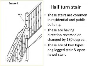
 Half-turn staircase
 Hey hey bye bye
 Dont ask why why why
 Megalocardia word breakdown
 Anova excel
 Shorter truth table
 Unlike traditional production rules, association rules
 Stairs 1-4 tavlebok
 Stair nosing australian standards
 One point perspective lettering
 Metric conversion staircase
 Metal pan stair
 Hamstring stretch stairs
 Stair construction terms
 Metric system stairs
 Metric system staircase
 Golden ratio the last supper
 Every flight of stairs with four or more risers
 Lang stair & rail inc
 Angle of stairs
 Climbing stairs java
 Follow the point
 Inverted arch footing
 Kangaroos hopping down mountains
 Four students run up the stairs in the time shown
 Stairs
 Madonna of the stairs
 David 1408
 A 680 newton student runs up a flight of stairs
 Tapiflex stairs
 Format output design
 Ground rules in a relationship
