Design of a Permanent Magnet Dipole For NTof


- Slides: 15

Design of a Permanent Magnet Dipole For N-Tof Experimental Area 1 to replace the existing M 200 electromagnet 29/05/2018 Pierre-Alexandre Thonet TE-MSC-MNC

Outline Ø Ø Ø Ø Ø A permanent magnet dipole For N-Tof Experimental Area 1 Requirements and constraints Dipole general view Permanent magnet material Magnetic design Protection covers Design report Budget and planning Conclusion and discussion Pierre-Alexandre THONET 29. 05. 2018 2

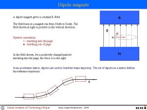
A permanent magnet dipole For N-Tof Experimental Area 1 • A dipole magnet is required after n. Tof target. It is used to evacuate all charged particles as protons and electrons from the neutron beam. Pictured: n_TOF line • Currently a 140 KW M 200 dipole magnet is installed in the n. Tof line to fill this function. • In the frame of the East area renovation a study is being done to replace M 200 magnets and DC power supplies by laminated M 200 magnets and cycled power supplies for energy savings. • Why a permanent magnet solution? Ø Taking in consideration the good feedback of the use of a permanent magnet dipole in n. Tof EAR 2, it was decided to study a permanent magnet solution as well for n. Tof EAR 1. Ø Reliability in radiation area. Ø Compact design. Ø Saving opportunities: o Cost of the magnet itself. o No power supply. o No external network such as electrical cabling and demineralized water. o No operational cost. Pierre-Alexandre THONET 29. 05. 2018 3

Requirements and constraints Units needed for n_TOF EAR 1 1 Integrated field ≥ 0. 6 T·m Aperture diameter ≥ 200 mm Good field region (GFR) diameter 200 mm Integrated field homogeneity in GFR ± 5 % Pierre-Alexandre THONET 29. 05. 2018 4

Dipole general view 200 mm 510 mm • In October 2017, 2 variant of dipole designs were presented: a solution based on an Halbach array and a design similar to the EAR 2 dipole. For permanent magnet blocks standardization and an easier assembly procedure, the second one was retained. • The magnet design is based on a iron dominated external yoke and poles and Samarium Cobalt Sm 2 Co 17 permanent magnet blocks. • Permanent magnet blocks installed between the external yoke and the poles act as magnetic flux generator. • Iron poles smooth possible deviations of permanent magnet blocks magnetization direction. 520 mm Pictured: layout of the permanent magnet dipole Pierre-Alexandre THONET 29. 05. 2018 5

Dipole general view Pictured: 3 D view the permanent magnet dipole Pierre-Alexandre THONET 29. 05. 2018 6

Permanent magnet material Samarium Cobalt Sm 2 Co 17 • Maximum specific energy product fulfils with the magnet design. • Small temperature coefficient: 0. 035%/°C. • Good radiation resistance. • Acceptable corrosion stability without protective coating. Sm 2 Co 17 grade Sm. Co 30 M • High remanent field Br=1. 1 T. • Small deviation of the magnetic characteristics (maximum 3% from the nominal values on Br and Hcb). • ± 5 deg maximum error of easy axis orientation. • Mechanical tolerance of the blocks: +/-0. 1 mm • Cobalt content in Sm 2 Co 17 magnets: ≈ 60 % • Magnets weight in the dipole: ≈ 626 kg Pictured: demagnetization curve of Sm. Co 30 M Pierre-Alexandre THONET 29. 05. 2018 7

2 D magnetic design By=0. 39 T Pictured: Field distribution Bmod (T) in the dipole Pictured: 2 D field homogeneity (By) inside the dipole aperture (%) Pierre-Alexandre THONET 29. 05. 2018 8

3 D magnetic design Pictured: Field distribution Bmod (T) in the dipole Pierre-Alexandre THONET 29. 05. 2018 9

3 D magnetic design Pictured: field integral (∫Bydz) homogeneity (%) inside the dipole aperture Pierre-Alexandre THONET 29. 05. 2018 10

Protection covers • For a safe handling and work activities in the vicinity of the dipole, some protection covers are needed at each extremities. They are here to create a physical barrier and avoid to approach a ferromagnetic tool close to the magnet. • Their length is defined in order to have a maximum field of 30 m. T outside the protection covers (this value was settled to provide acceptable conditions for handling ferromagnetic equipment in this field but is not related to protection of persons which has restrictions to magnetic fields exposure higher than 0. 5 m. T). • This results in protection covers 180 mm long. The overall length of the dipole including the covers is then 1900 mm. Bmod<30 m. T Pictured: positioning of protection covers Pierre-Alexandre THONET 29. 05. 2018 11

Parameter table Magnet Type Aperture diameter Total magnet length Total magnet width × height Total magnet mass Dipole 200 1900 520 x 510 2600 mm mm mm × mm kg Pure iron / AISI 1010 1540 mm Sm 2 Co 17 30 626 MGOe kg T T·m Magnetic length 0. 39 0. 617 1582 GFR radius Integrated field homogeneity in GFR Integral field error (rms) 100 ≤ ± 3 ≤ ± 2 mm % % Yoke Steel type Iron length Permanent magnets Permanent magnet material BH max Mass of permanent magnet Magnetic field Nominal field at the centre Nominal integrated field Pierre-Alexandre THONET 29. 05. 2018 mm 12

Design report • The design report of the dipole is going to follow the approval process in EDMS from end of May 2018. Pierre-Alexandre THONET 29. 05. 2018 13

Budget and planning Component Cost (CHF) Permanent magnet blocks 60000 Machining of magnetic and non-magnetic parts 40000 Assembly of the magnet 20000 Contingency 10000 TOTAL COST 130000 CHF The cost of this solution is much lower than manufacturing a new electromagnet with its power supply and electrical/water network (≈400 k. CHF) to which the operational cost shall be added. Activity Date Validation of the permanent magnet solution February 2018 Validation of the design June 2018 All orders sent out July 2018 All parts received at CERN October 2018 Magnet assembled and measured February 2019 Pierre-Alexandre THONET 29. 05. 2018 14

Conclusion and discussion • The proposed design meets the requirement in term of integrated field (0. 6 T·m) and field homogeneity (+/-3%). • Discussion about installation and positioning of the magnet in the n_TOF target area. • Where does the technical specification shall be attached to in MTF? List of persons for document checking? • Budget and planning. Pierre-Alexandre THONET 29. 05. 2018 15
 Ion-dipole interaction example
 What happens when you break a magnet in half
 Temporary vs permanent magnets
 Induced dipole
 Dipole induced dipole forces
 Dispersion forces vs dipole dipole
 Capillary action
 Intermolecular forces formaldehyde
 Van der waals forces diagram
 Surface tension intermolecular forces
 Induced dipole
 Dipole-dipole attractions
 Intermolecular forces
 London forces vs van der waals
 Hydrogen bonding intermolecular forces
 Instantaneous dipole
