Data Communication Networks Lec 13 and 14 Network


")


- Slides: 47
Data Communication Networks Lec 13 and 14
Network Core- Packet Switching
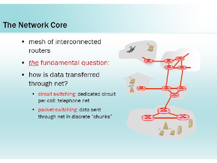
Switching Networks �Long distance transmission is typically done over a network of switched nodes �Nodes not concerned with content of data �End devices are stations ◦ Computer, terminal, phone, etc. �A collection of nodes and connections is a communications network �Data routed by being switched from node to node
Simple Switched Network
Taxonomy of switched networks
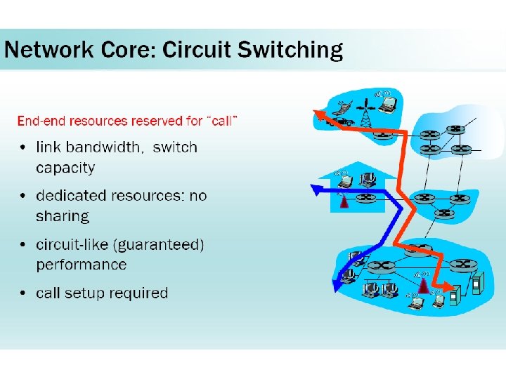
CIRCUIT-SWITCHED NETWORKS A circuit-switched network consists of a set of switches connected by physical links. A connection between two stations is a dedicated path made of one or more links. However, each connection uses only one dedicated channel on each link.
Figure A trivial circuit-switched network
Circuit Switching • Three phases – Establish – Transfer – Disconnect • Must have switching capacity and channel capacity to establish connection • Must have intelligence to work out routing
Note In circuit switching, the resources need to be reserved during the setup phase; the resources remain dedicated for the entire duration of data transfer until the teardown phase.
Example 8. 1 let us use a circuit-switched network to connect eight telephones in a small area. Communication is through 4 -k. Hz voice channels. The bandwidth of each link is then 8 k. Hz. Figure 8. 4 shows the situation. Telephone 1 is connected to telephone 7; 2 to 5; 3 to 8; and 4 to 6. Of course the situation may change when new connections are made. The switch controls the connections.
Figure 8. 4 Circuit-switched network used in Example 8. 1
Example 8. 2 As another example, consider a circuit-switched network that connects computers in two remote offices of a private company. The offices are connected using a T-1 line leased from a communication service provider. There are two 4 × 8 (4 inputs and 8 outputs) switches in this network. For each switch, four output ports are folded into the input ports to allow communication between computers in the same office. Four other output ports allow communication between the two offices. Figure 8. 5 shows the situation.
Figure 8. 5 Circuit-switched network used in Example 8. 2
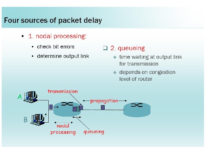
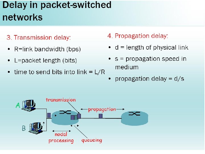
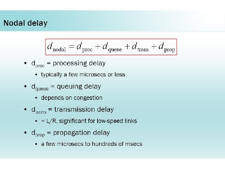
Figure Delay in a circuit-switched network
Note Switching at the physical layer in the traditional telephone network uses the circuit-switching approach.
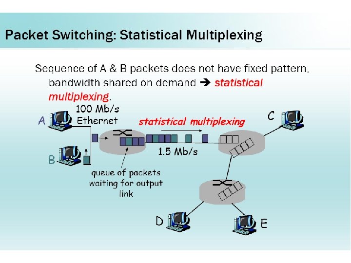
Packet Switching Note In a packet-switched network, there is no resource reservation; resources are allocated on demand.
Basic Operation • Data transmitted in small packets – Longer messages split into series of packets – Each packet contains a portion of user data plus some control info • Control info – Routing (addressing) info • Packets are received, stored briefly (buffered) and pass on to the next node – Store and forward
Use of Packets
Advantages • Line efficiency – Single node to node link can be shared by many packets over time – Packets queued and transmitted as fast as possible • Data rate conversion – Each station connects to the local node at its own speed – Nodes buffer data if required to equalize rates • Packets are accepted even when network is busy – Delivery may slow down • Priorities can be used
Packet Switching Technique • Station breaks long message into packets • Packets sent one at a time to the network • Packets handled in two ways – Datagram – Virtual circuit
DATAGRAM NETWORKS In data communications, we need to send messages from one end system to another. If the message is going to pass through a packet-switched network, it needs to be divided into packets of fixed or variable size. The size of the packet is determined by the network and the governing protocol.
Datagram • • • Each packet treated independently Packets can take any practical route Packets may arrive out of order Packets may go missing Up to receiver to re-order packets and recover from missing packets
Figure A datagram network with four switches (routers)
Datagram Diagram
Note A switch in a datagram network uses a routing table that is based on the destination address.
Note The destination address in the header of a packet in a datagram network remains the same during the entire journey of the packet.
Figure 8. 9 Delay in a datagram network
Note Switching in the Internet is done by using the datagram approach to packet switching at the network layer.
Packet Size
8 -3 VIRTUAL-CIRCUIT NETWORKS A virtual-circuit network is a cross between a circuitswitched network and a datagram network. It has some characteristics of both.
Virtual Circuit • Preplanned route established before any packets sent • Call request and call accept packets establish connection (handshake) • Each packet contains a virtual circuit identifier instead of destination address • No routing decisions required for each packet • Clear request to drop circuit • Not a dedicated path
Figure 8. 10 Virtual-circuit network
Figure 8. 11 Virtual-circuit identifier
Figure 8. 12 Switch and tables in a virtual-circuit network
Figure 8. 13 Source-to-destination data transfer in a virtual-circuit network
Figure 8. 14 Setup request in a virtual-circuit network
Figure 8. 15 Setup acknowledgment in a virtual-circuit network
Note In virtual-circuit switching, all packets belonging to the same source and destination travel the same path; but the packets may arrive at the destination with different delays if resource allocation is on demand.
Virtual Circuit Diagram
Figure 8. 16 Delay in a virtual-circuit network
Note Switching at the data link layer in a switched WAN is normally implemented by using virtual-circuit techniques.