Cryogenic Energy Storage Daniel OGrady Outline History of

 Process of CES Advantages/disadvantages of CES Current")

 1965 – Vapor cooled radiation shields 1970 – Vapor cooled")


")


- Slides: 16
Cryogenic Energy Storage Daniel O’Grady
Outline History of Cryogenics/Cryogenic Energy Storage (CES) Process of CES Advantages/disadvantages of CES Current operating plant Future plans
History of Cryogenics 1887 - Cailletet and Pictet liquefied oxygen 1892 – Sir James Dewar developed a vacuuminsulated vessel for storage of cryogenic fluids 1902 – Georges Claude developed the first airliquefaction system using an expansion engine 1916 – First commercial American-made air liquefaction plant completed 1939 – First vacuum-insulated railway tank car built for transport of liquid oxygen
History of Cryogenics (continued) 1965 – Vapor cooled radiation shields 1970 – Vapor cooled necks 1975 – Multi Layer Installation (MLI) 1983 – Infrared Astronomical Satellite (IRAS) 2000 – Space probes
Liquid Air 78% Nitrogen, 21% Oxygen, 1% Argon Boiling temperature of 78. 8 K at Atmospheric pressure Dry air has a density of 1. 225 kg/m^3 Liquid air has a density of 870 kg/m^3 Dry air can be cooled using a simple three stage process called the Hampson–Linde cycle
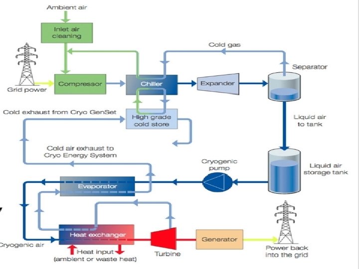
How does LAES Work? Three step process Charging Storage Recovery Capture of waste heat at all steps in the process Coupled with other industrial processes to further increase efficiency
Charging (Hampson–Linde Cycle)
Storage Stored in insulated tanks at atmospheric pressures Potential to store up to GWth of liquefied air Process is currently used to store liquid natural gas (LNG) Cryogenic transportation is already established throughout the industry Allows for the possibility of a mobile remote back -up power system
Recovery At times of peak demand the liquefied air would be pumped through a heat exchanger As the air is allowed to warm up it will rapidly boil and increase in pressure The boiling air can then be used to spin a turbine and produce electricity
Advantages Proven technology that has been around since the early 1900 s Regulations for Cryogenic storage already exist Stored at low pressure Non toxic and does not explode Four times the energy density of regular air No geology required
Disadvantages Over long periods of time nitrogen can boil off resulting in an oxygen rich liquid Efficiency is largely dependent on coupling with external sources. 25% efficient Storage ranges from 2 - 20 hours
Pilot Plant 350 k. W, 2. 6 MWh storage capacity Developed by the University of Leeds and Highview Power Storage Operates in conjunction with a 80 MW biomass power station in Slough, UK since 2010 Current efficiency of 15% Virtual tour
Future Plans Highview Power Storage was recently selected by one of the UK to design a 5 MW/15 MWth LAES system Plant will recycle all of its cold waste Incorporated with a landfill gas generation plant
References http: //www. modernpowersystems. com/features/featur ehighview-prepares-for-the-next-step-in-liquid-airtechnology-development-4824865/ http: //zebu. uoregon. edu/disted/ph 162/l 8. html http: //www. gizmology. net/liquid_air. htm https: //www. cryogenicsociety. org/resources/cryo_cent ral/history_of_cryogenics/ http: //www. highview-power. com/tour/