CRYOGENIC INSTRUMENTATION International Workshop on Cryomodule Design and


 General Industrial Pressure Processes Flow Temperatures")


")


")


 Stability")


- Slides: 27
CRYOGENIC INSTRUMENTATION International Workshop on Cryomodule Design and Standardization September 4 -9, 2018 BARC - Mumbai Shrikant Pattalwar STFC Daresbury Laboratory (UK)
SRF at STFC Daresbury Laboratory • ALICE 35 MEV Energy Recovery Accelerator Based on 4 x 1. 3 GHz SRF cavities (2005 – 2012) • 1. 3 GHz ERL Cryomodule Collaboration for High Current and CW applications (STFC, Cornell, LBNL, SLAC, DESY, HZDR, TRIUMF) (2008 - 2013) • SRF Crab Cavities for Hi Lumi HLC (CERN, STFC, AUP-US) Prototypes/ Pre Series CMs for DQW and RFD (2010 –ongoing) Series CMs for DQW (2020 onwards) • ESS – High beta cavities (2015 – ongoing) • PIP-II (2019 onwards) 2
Cryogenic Instrumentation • Introduction • Thermometry • Some Examples • Potential R&D topics • Discussion and Summary 3
Introduction Like any other control and measurement operations in industrial or scientific environment cryogenic processes are also developed around a range of sensors and actuators. Basic focus of the process development is on Safety Reliability Efficiency of people, environment and equipment of operations, measurements to keep overall costs down Essential Desirable Balance between automation and manual Seek more information, future improvements ( R&D) 4
Typical parameters to be measured and controlled • • • Temperature Pressure (from Vacuum to high pressures) Flow Level Alignment Power Valve positions Measuring instruments …. The technology to deal with most of the above parameters is well established, standardised with unlimited choices. But, Cryogenic thermometry needs special attention 5
Why is Cryogenic Instrumentation different? 10000 T (K) General Industrial Pressure Processes Flow Temperatures ( Thermocouples, RTD) 300 K …. . 1000 Valves Measuring Instruments Feedthroughs 100 Technology changes every two decades in temperature Cryogenics Temperature sensors LHe-level probes ( SC) Piezo tuners Strain gauges Cryogenic Processes Feedthroughs ……. 10 ………. . 1 0 0. 1 1 2 3 4 5 6 7 6
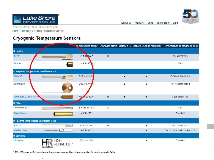
Why is cryogenic thermometry different? • • • Material properties, change drastically Sensitivity of conventional (Industrial) temperatures sensors (RTD, Thermocouples, …) becomes extremely poor at cryogenic temperatures (T< 50 K) Heat Capacity (thermal mass) of material reduces by several orders of magnitude (the Debye T 3 law) If a 1 W/1 s heat pulse to a 5 g of copper block at 300 K, it wont’ even be detected But the same heat pulse at 2 K can easily create a large temperature excursion of few degrees! Small heat leaks are the primary sources of errors in the measurements… a heat source few n. W can kill the measurements and therefore must be identified and managed carefully A typical PT 100 (RTD) is measured using an excitation current of 1 m. A/ 0. 1 m. A with a self heating at RT is ~ 10 -4 W A typical Cernox is measured using an excitation current of 10 m. A/ 1 m. A with self heating of ~ <10 -7 W >> signal levels to be handled are very low and stabilities required are very high 7
Sources of Errors Measurements Very low excitation levels (1 m. A, 1 m. V full scale) Stabilities required are very high (1 in 10, 000) Thermo-emf >> current reversal / ac measurements Each sensor requires individual calibration All this requires special instrumentation Lakeshore, Cryocon, OI, CEA, ……. . Choice of wiring and sensor mounting A range of materials is used for wiring and it is important to choose that is the most appropriate for your experiment. Well addressed by industry Rely on local expertise, SOP. . , skills and varies significantly from lab to lab Optimised wiring for a cryostat is often the result of a compromise between thermal and electrical requirements of the system.
Ref: Practical Cryogenics by OI
Economics TI 8018 TI 8014 TI 8081 TI 8084 TI 8083 TI 8034 TI 4351 A TI 8064 TI 4352 A TI 8058 TI 8028 Thumb Rule Capital Cost $1000/ parameter TI 8021 -24 TI 8086 TI 8011 TI 8010 TI 8012 TI 8013 TI 8015 TI 8082 TI 8085 TI 8017 (ERL Cryomodule) TI 8019 TI 8020 TI 8016 TI 8051 -54 TI 8006 TI 8004 TI 8002 TI 8001 TI 8008 TI 8003 TI 8007 TI 8005 PT 100 CLTS CERNOX CX 1050 Cernox
Sensor Mounting Heat conduction to sensing element is always higher through its leads than its interface (the bonding/ glue) Stycast GE varnish Apiezon – N Thermal Anchoring to intercept the heat flow close to the heat sink and To reduce measurement errors close to thermometer Ref: Practical Cryogenics by OI
Sensor mounting Thermal Anchoring to intercept the heat flow close to the heat sink and To reduce measurement error close to thermometer Mounting hole Wiring bobbin sensor
Manganin Twisted pair Ribbon (Tekdata)
Example : ERL Cryomodule Accelerator and Lasers in Combined Experiment Dimensioned to fit on the ALICE ERL facility at Daresbury: – Same cryomodule footprint. – Same cryo/RF interconnects. – ‘Plug Compatible’ with existing cryomodule
ERL Cryomodule HOM absorbers
Message for Standardisation Consideration to sensor mounting and thermal anchoring should be given at the mechanical design stage Cavity- helium vessel, couplers, shields, ……. . • Clearly specify/define locations • Provide suitable mounting holes/clamps for sensors, bobbins, wiring In most of the cased these sensors are glued to the surface with Stycast, GE Varnish, Apiezon grease, Indium….
Vertical Test Facility at Daresbury
P&ID (Process and Instrumentation Diagram)
P&ID
Essential vs Desirable TI 8018 TI 8014 TI 8081 TI 8084 TI 8083 TI 8034 TI 4351 A TI 8064 TI 4352 A TI 8058 TI 8028 Thumb Rule Capital Cost $1000/ parameter TI 8021 -24 TI 8086 TI 8011 TI 8010 TI 8012 TI 8013 TI 8015 TI 8082 TI 8085 TI 8017 TI 8019 TI 8020 TI 8016 TI 8051 -54 TI 8006 TI 8004 TI 8002 TI 8001 TI 8008 TI 8003 TI 8007 TI 8005 PT 100 CLTS CERNOX CX 1050 Cernox
Cryogenic Performance COOL DOWN to 2 K 295 K 130 K Cryogenic (Pressure) Stability at 2 K 3 K/hr (Cooling only by Thermometers are critical radiation and conduction during supports) Cooldown through 2 ½ days to 130 K 15 hrs to 4 K Cavity 1 3 hrs to 2 K Pressure measurement is critical in equilibrium Cavity 2 2. 0 K Liquid Helium levels in Reservoirs Cavity 1 Cavity 2 Level Control Valve 14 th June 2013 Cavity 1 Service Reservoir Cavity 2
Cryogenic temperature sensor based on Fibre Bragg Grating Good for measuring temperature profile • Wavelength shift is influenced by both strain and temperature Advantages: Fibre optic interrogator • • • The response time is superior than thermistors or ordinary Platinum resistors Inexpensive and robust Easy to install Can get the exact position (sub-mm range), Can measure temperature between - 140 C to 600 C. Relation between wavelength and temperature: Thermo-optic coefficient of the FBG will not change, however, thermal expansion properties will change E S de L Filho et. al, Optics Express, vol 22 No. 22, 2014
Cryogenic temperature sensor based on Fibre Bragg Grating • It has been used for T > 40 K • Will be very economic and simple • FPG technology must be explored for measuring temperature profiles (e. g. quench detection) • R&D needed to extend the temperature range for SRF applications
Remarks and Summary • As far as possible keep the process simple • Use well demonstrated industrial components and processes to keep the cost down with high reliability • Identify what is essential/ desirable (R&D vs Operations) • Consider redundancies (Replacement of sensors not possible) • In SRF based accelerators temperatures sensors are critical for cool-down, warm –up, interlocks…. • At equilibrium temperatures vapour pressure is the best indicator of temperature
Remarks and Summary • Cryogenic Instrumentation is similar except for thermometry and few other devices that actually operate in cryogenic environment. • Careful consideration must be given to wiring and sensor mounting at the design stage • Several devices/ components could not covered in the presentation due to time limitations … Feedthroughs, SC level probes, Cold valves, etc.
Questions / Discussion 27