CRUISE CONTROL SYSTEM FIRAS FAWAZ SOBUH ABD ALRAHMAN

CRUISE CONTROL SYSTEM FIRAS FAWAZ SOBUH ABD AL-RAHMAN ZAID AL-KILANI

• Introduction • Equipments • Principle of work • Measuring • Matlab & simulink • Root-locus

INTRODUCTION • cruise control system has become a common feature in automobiles nowadays. Instead of having the driver frequently checking the speedometer and adjusting pressure on the gas pedal or the brake. • cruise control system control the speed of the car by maintaining the constant speed set by the driver. Therefore, cruise control system can help reduce driver’s tiredness in driving a long road trip. • Before getting into to the control system concepts of cruise control, the components and the basic mechanism of the cruise control system in a vehicle are summarized:

COMPONENTS • Cruise control system can be divided in to three main parts, which are the input, the processor, and the output. The input of the system includes the setting buttons on the steering wheel, gas pedal, brake, clutch and the feedback signal of the cruise control. The processor of the system is to control the speed of the car by utilizing the control system theory. The output is the throttle position, which is corresponding to the actual speed of the car.

INPUT OF CRUISE CONTROL: There are usually three to five setting buttons on the steering wheels for the input to the cruise control system. The buttons are ON/OFF, SET/ACCEL, RESUME, and COAST. • The ON button turns on the cruise control function. • The OFF button turns off the cruise control function. • The SET/ACCEL button is to set the speed of the car to the current speed that the car is driving at. Also, by tapping the SET/ACCEL button once can increase the speed of the car by 1 mph (1. 609344 km/h).

• The RESUME button is to set the speed of the car back to the last maintained speed, which is the speed right before the cruise control is disengaged. • The COAST button is to decrease the speed of the car. • The brake and the clutch are the other inputs to the cruise control system. When the pedal is pressed, the cruise control system is disengaged, so the speed control of the car is taken over by the driver in adjusting the gas pedal and the brake.

Furthermore, the speed for the cruise control can be set by pressing the gas pedal to accelerate the car to the desired speed, and then hitting the set button. Also, when the cruise control is engaged, the gas pedal overrides the set speed from the cruise control, so the car accelerates as long as the gas pedal is pressed.

PROCESSER The processor of a cruise control is a control system designed to obtain the speed set by the driver. It plays an important role in the cruise control system. The processor is integrated with electronic components to a system transfer function, which is discussed under the control system of cruise control in detail.

The output of the cruise control is the throttle position. The actual speed of the car varies corresponding to different throttle position, as the throttle valve limiting how much air the engines takes in. A different air-to-fuel ratio in the combustion process affects the power and the speed of the engine, and this eventually leads to the change of the car speed.

MECHANISM OF CRUISE CONTROL The relationship between different components of cruise control system is shown in Figure above. The processor of the cruise control system is shown as the Cruise Control Computer in the figure. The process of the cruise control system in a vehicle is: First, the driver sets the wanted speed of the car by turning on the cruise control at the wanted speed that the car is traveling at and hit the set button. An alternate way to set the wanted speed of the car is by tapping the SET/ACCEL button to increase the speed of the car or by tapping the coast button to decrease the speed of the car.

Second, the processor of the system gets the input signal, and then sends the output signal to the actuator. Third, the actuator adjusts the throttle position. Finally, the changes in the throttle position would leads to the changes in the speed of the car traveling. Also, the actual speed of the car is measured by a sensor and sent to the processor. The process of sending the current speed of the car continues for the processor to maintain the desired speed, as long as the cruise control is engaged. The throttle valve connects to the actuator and the gas pedal by cables, so the throttle position can be adjusted by the actuator and the gas pedal. Some actuators are powered by the engine vacuum to close and open the throttle. The pulse frequency corresponding to the speed of the car is sent to the vacuum controlled diaphragm conned to the accelerator, and it regulates the amount of the vacuum the diagram received.

The throttle valve connects to the actuator and the gas pedal by cables, so the throttle position can be adjusted by the actuator and the gas pedal. Some actuators are powered by the engine vacuum to close and open the throttle. The pulse frequency corresponding to the speed of the car is sent to the vacuum controlled diaphragm conned to the accelerator, and it regulates the amount of the vacuum the diagram received.

MEASURING TOOLS The distance driven by the car is measured by comparing the number of times the front axle has turned to the number of rotations per kilometer, called the calibration factor. The speed is obtained by dividing distance by time. The CCS has to compute the speed regularly and display it on the dashboard. For the driver’s comfort, it is necessary to compute the speed of the car every second. If this period were longer, the Cruise Control System would cause the car to change speed jerkily.
")
TOYOTA’S CRUISE CONTROL (VIDEO)

CONTROL

MODELING The system is a first-order mass-damper system. Summing forces in the x-direction and applying Newton's 2 nd law, we arrive at the following system equation: mv +bv=f Since we are interested in controlling the speed of the vehicle, the output equation is chosen as follows y=v

TRANSFER FUNCTION

PARAMETERS The parameters used : M vehicle mass 1750 kg B damping coefficient 50 N. s/m F force 780 N

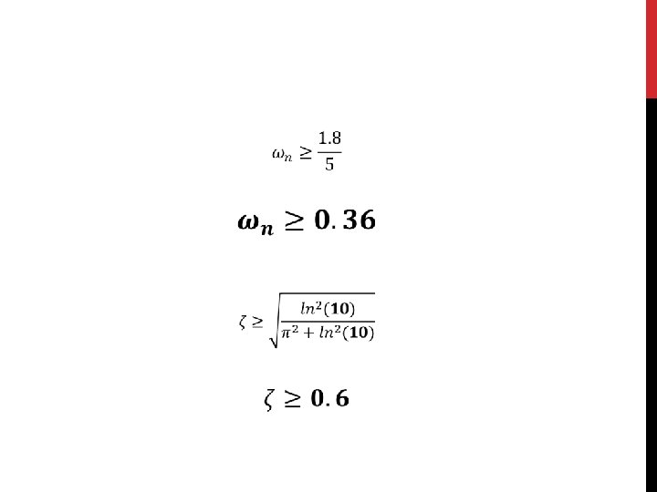
PERFORMANCE SPECIFICATIONS Performance specifications The design criteria that the compensated system should achieve. When the engine gives a 780 Newton force, the car will reach a maximum velocity of 15. 6 m/s. An automobile should be able to accelerate up to that speed in less than 5 seconds. In this application, a 10% overshoot and 2% steady-state error on the velocity are sufficient. Keeping the above in mind, we have proposed the following design criteria for this problem: • Rise time < 5 s • Overshoot < 10% • Steady-state error < 2%

OPEN-LOOP STEP RESPONSE Via MATLAB m = 1750; b = 50; f = 780; num = [f]; den = [ m b]; sys=tf(num, den); step(sys)

We see that the open-loop system is a first-order system which has no overshoot or oscillations, and does reach the desired steady-state speed of 15. 6 m/s; however, the rise time is much too slow, ~77 s. Therefore we need to design a feedback controller which speeds up the response significantly without negatively affecting the other specification.

OPEN-LOOP BODE PLOT We see that the Bode plots exhibit the definitive features of first -order systems, including a -3 d. B magnitude and 45 deg phase at the corner frequency of w = b/m = 0. 028 rad/s and 20 d. B/dec roll-off at high frequencies.

ROOT LOCUS DESIGN

PROPORTIONAL CONTROL

Via MATLAB we obtain the Value of Kp m = 1750; b = 50; num=[1]; den=[m b]; sys = tf(num, den); rlocus(sys) axis([-0. 6 0. 6]); sgrid(0. 6, 0. 36) [Kp, poles]=rlocfind(sys) Kp = 822. 1036

RESPONSE TO THE KP CONTROLLER FIGURE Via MATLAB m = 1750; b = 50; r=15. 6; num=[1]; den=[m b]; sys = tf(num, den); Kp = 822. 1036; ksys = feedback(Kp*sys, 1); t = 0: 0. 1: 20; step(r*ksys, t)
")
With the gain Kp we just chose, the rise time (less than 5 sec) and the overshoot criteria have been met; however, a steady-state error haven’t.

LAG CONTROLLER

the pole and the zero of a lag controller need to be placed close together. Also, the steady-state error will be reduced by a factor of zo/po. so, let zo equal 0. 3 and po equal 0. 03.
![m = 1750; b = 50; num=[1]; den=[m b]; sys = tf(num, den); zo](http://slidetodoc.com/presentation_image_h/e87829a298eead05066bc816d5846439/image-32.jpg "m = 1750; b = 50; num=[1]; den=[m b]; sys = tf(num, den); zo")
m = 1750; b = 50; num=[1]; den=[m b]; sys = tf(num, den); zo = 0. 3; po = 0. 03; numl=[1 zo]; denl=[1 po]; lag 1 = tf(numl, denl); rlocus(lag 1*sys); axis([-0. 6 0 -0. 4]) sgrid(0. 6, 0. 36); [Kp, poles]=rlocfind(lag 1*sys) Kp = 1939. 1

CONTROLLER RESPONSE As you can see, the steady-state error has been reduced to near zero. The overshoot is a result of the zero added in the lag controller. For now all of the design criteria have been met and no further iterations are needed.

PID An easy way to design the controller using the MATLAB’s PID function as shown in the figure below Clicking on the PID Controller will yield us the Function Parameters window.

Clicking on the Tune button , will yield us the next window shown in the figure , then we choose the rise time we want (less than 5 seconds)

Depending on the criteria we choose the MATLAB we calculate P, I and D values P= 855. 152192404221 I= 39. 6317355896807 D= -867. 95455244251

The Scope graph is shown below
- Slides: 37