Common Mode Voltage in Power Converters Definition of


 do not allow")


- Slides: 23
Common Mode Voltage in Power Converters
Definition of common mode voltage • The CMV in power converter systems is defined in the same way as in electronics: the average of the voltage of each line with respect to the local common or ground. In a two-wire cable, a CMV appears on both lines, in-phase and with equal amplitudes.
Single phase bridge converter In power converter systems, the switching action of solid-state devices is a main source of CMVs. The CMV is defined with respect to the dc-link midpoint. With bipolar modulation that simultaneously turns on or off the diagonal switches (S 1 and S 2, S 3 and S 4), the CMV is always kept at zero. However, unipolar PWM generates a stepwise CMV waveform with the values of ±vdc/2 and 0.
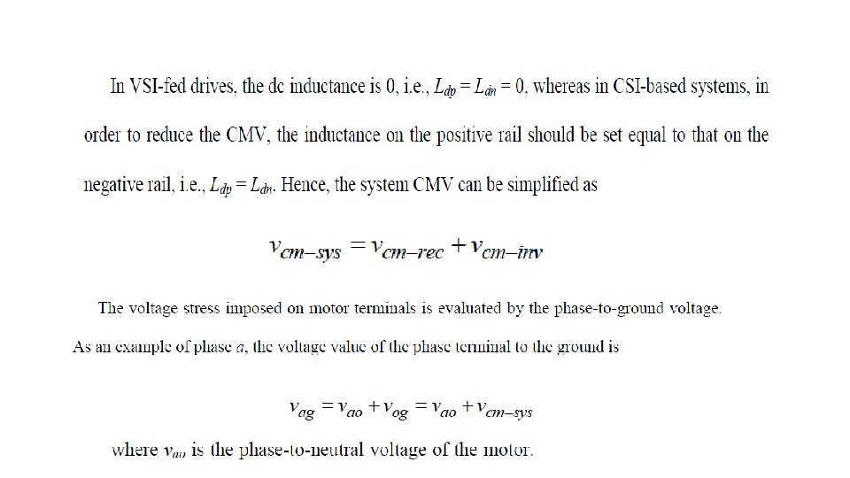
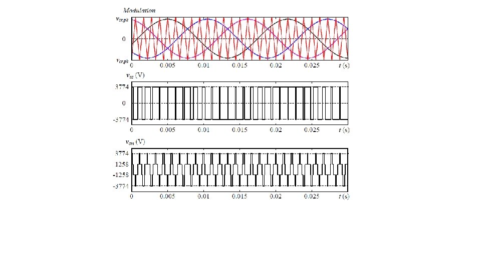
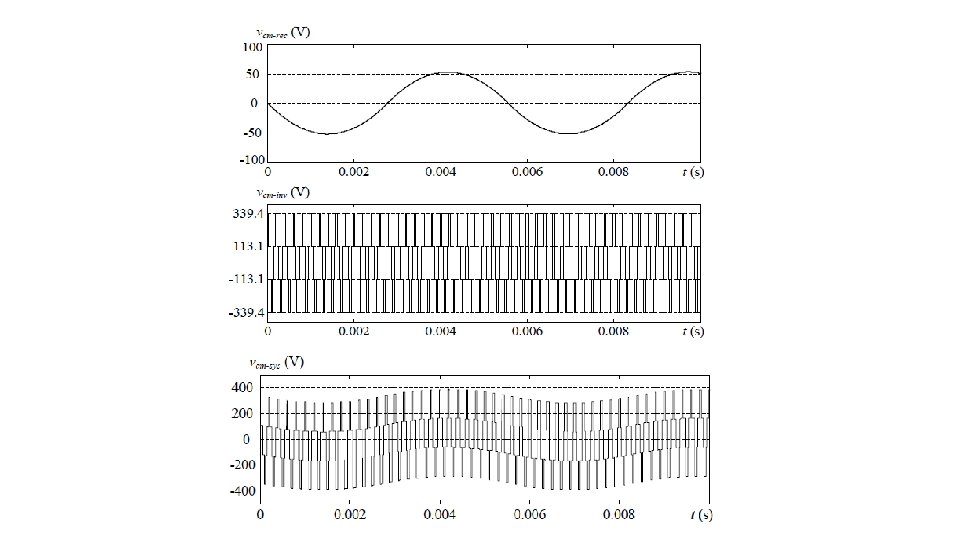
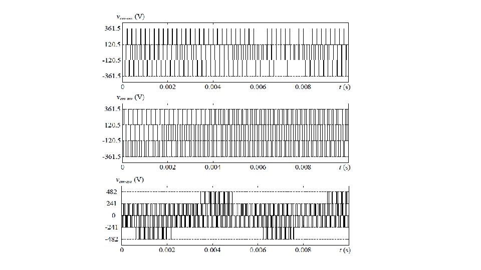
Three-phase bridge converter • The CMVs are essentially zero-sequence components in three-phase systems and equal to zero with a balanced supply and load. This is different from the single-phase full-bridge converter. It could never be zero. Three-phase VSC’s CMV is defined by
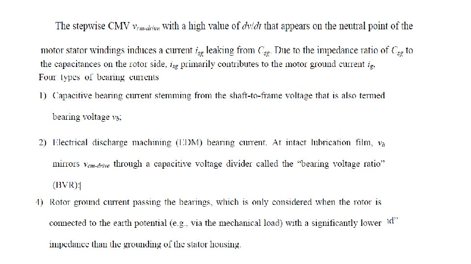
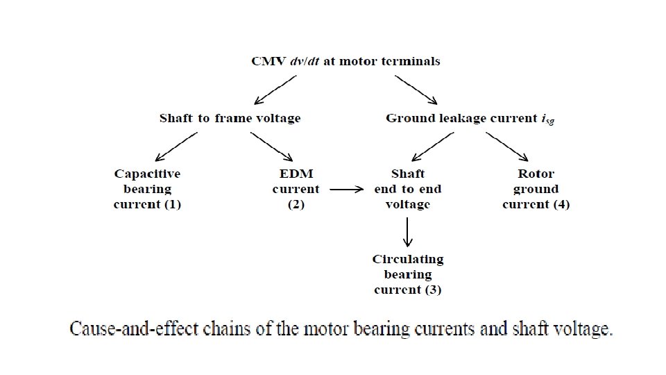
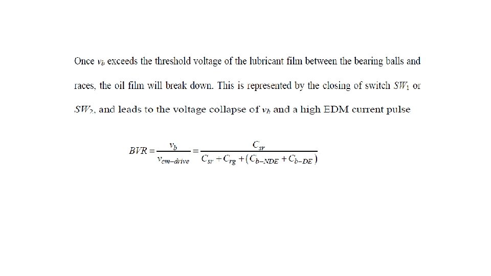
If CMVs are not mitigated in a motor drive, they will appear on the neutral point of the stator windings with respect to the ground. The motor line-to-ground voltage, which is originally equal to the line-to-neutral (phase) voltage, can be substantially increased, leading to premature failure of the motor winding insulation system. As a result, the motor life expectancy is shortened.
The MV drives (2. 3 k. V– 13. 8 k. V) do not allow their motors to be subjected to any CMVs; otherwise replacement of damaged motors would be very costly in addition to causing loss of production. The CMV stress, on the other hand, is often neglected in lowvoltage (LV: ≤ 600 V) drives. The conservative insulation design of LV motors supports it. However, the other CMV issues induced via the parasitically capacitive couplings inside the motor, including the shaft voltage, ground and bearing currents, exist in both MV and LV drives, and can not be ignored.
CM-circuit model of a machine
Thyristor controlled rectifier
CMV for diode rectifier with capacitive load
CMV for thyristor rectifier with inductive load firing angle=60 degrees
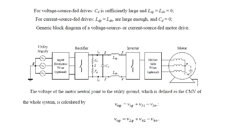
Simplified circuit diagram of VSI-fed drives
VSI-fed motor drive with a diode-front end
Back-to-back PWM VSC-based motor drive