Coachella Valley Water District Water Service and Water


- Slides: 19

Coachella Valley Water District Water Service and Water Meter Sizing Criteria Workshop April 13 th from 10: 30 -11: 30 am April 19 th from 1: 30 -2: 30 pm CVWD Engineering Domestic Water Engineering Development Services 1

Agenda • • Introduction Background CVWD Domestic Water System Guidelines for Water Service and Meter Sizing Design by the EOR • Examples • Revised Meter Application Process • Questions 2

Background 2010 California Residential Code The California Building Standards Commission approved and adopted the 2010 California Residential Code (California Code of Regulations, Title-24, Part 2. 5) based on the 2009 edition of the International Residential Code (published by the International Coe Council) with an effective date of January 1, 2011. The provisions of Sections R 313. 1 (Townhouse) and R 313. 2 (One- and two-family dwellings) reads: “An automatic residential fire sprinkler system shall be installed in townhouses and in one- and two-family dwellings” respectively. Additional Information • NFPA 13 D • AWWA M 6 • CVWD – Development Design Manual 3

Current Process 1. Water Plans Designed (No calculation on service size) 2. Project is Constructed 3. Request for Service 4. Engineer, Developer or Customer provides Domestic Water Demands (Max Flow/Min. Pressure) 5. Service under sized for requested flow/min pressure NEXT Tract No. Dwg No. XXXXXX 1” Service W/3/4” Meter Agreement 4

Permanent Service Connection Installation Charges Upsizing Service Costs Example From the water plans ¾”M/1”S to a 1”M/1 ½“S Abandon Existing service = $600+ Install new 1 ½“ Service Line = $3, 510 1” Meter = $400 Meter Surcharge = $2, 479 Total = $6, 989 + Additional Impacts 1. Delay in receiving Domestic Water Service 2. Must schedule CVWD to remove existing service and install new service line and meter 3. Requires pavement to be cut and patched E 5

Benefits of New Process for Water Service and Water Meter Sizing • Reduces inaccuracy of meter and service line sizing • Speeds up processing of Residential Connection Charge Estimate – Reduces time to review meter installation requests (check plans for meter size, demands and minimum pressure) – Avoids multiple resubmittals (2 to 3 weeks+) • Avoids costly upsizing of service line size • Avoids delays to schedule the removal and upsizing of the existing service line • Avoids cutting new street pavement 6

CVWD Domestic Water System Pressure Zones • 69+ Pressure Zones E 7

CVWD Domestic Water System Sub-Pressure Zones 8

Static Pressure Zone hydraulic grade line (HGL) The location of a reservoir is dictated by the hydraulic grade line (feet above MSL) of the pressure zone when the reservoir is empty (base elevation). CVWD requires a minimum static pressure of 60 psi at all points within the development based on the elevation of the reservoir. Reservoir heights are generally 24 or 32 feet. 9

Calculate Pressure Loss • • Corporation Stop Copper (Type K) Service Line Fittings Angle Meter Stop Water Meter Straight Check Valve Shut-off valve Also See • • E AWWA M 6 Table 3 -3 DDM CVWD’s approved material list Manufacture Specification Sheet CVWD Standard Drawings • W-7 Detail of 1” Service Connection and Meter Installation • W-9 Detail of 1 ½” Service Connection and Meter Installation • W-11 Detail of 2” Service Connection and Meter Installation 10

Water Service And Water Meter Sizing Criteria • Lot No. PZ (HGL) + ½ Res Ht (E) Meter Elev. Domestic Water Service Meter and Service Run Table Service Static Fire Sprinkler Domestic Water Run Pressure Demand/Pressure Length at meter (gpmmax/psimin) (ft) (psi) / / / Customer Side of Meter Pressure Service Run Size (inches) DW Service Meter Size 11

4. 5. 6. Determine the service run length from the domestic water main to the meter Determine worst case condition of the Fire Sprinkler or Domestic Water demand pressure The EOR must determine the total head loss (in psi) at the required critical gpm flow rate. Losses typically include the following: a. Meter – Head loss based on the proposed meter b. Service line – Head loss based on the proposed service line size c. Fittings – Head losses from all fittings and valves to the customer side of the meter d. Head losses from backflow devices or other appurtenances 7. Subtract all head losses from the static pressure to determine the available pressure on the customer’s side of the meter. If the available pressure or flow on the customer’s side of the meter is less than the worst case required pressure and/or flow, repeat the calculations using the next larger meter/service line combination size. Repeat process until the required pressure and flow criteria is satisfied. 8. Also refer to the California Residential Code, Title 24, Part 2. 5, R 313 and NFPA - 13 D, for additional information regarding the sizing of service lines. 12

Additional Information Typical service/meter combinations are as follows, although other combinations may be approved subject to CVWD’s discretion. However, meter sizes cannot exceed the service line size. 1" service 1. 5" service 2" service 3/4" meter 1. 5" meter 2" meter Type K Copper information: Size 5/8" 3/4" 1" 1 1/2" 2" CHW 130 130 130 I. D. 0. 652 0. 745 0. 995 1. 481 1. 959 Typical fittings that are included in the head loss calculations include corporation stops, angle meter stops, ball valves, and check valves. See the manufacturer’s data sheets for head loss factors. Refer to CVWD’s “Approved List of Materials” for approved products. This information may be found at our website at http: //www. cvwd. org/208/Development-Design-Manual. CVWD currently uses the following meters. See the manufacturer’s head loss curve tables to determine the head loss through the meter at the required flow rate: • • E Master Meter – 3/4” Multi-Jet Meters (max. 30 gpm) Master Meter - 1” Multi-Jet Meters (max. 50 gpm) Master Meter – 1 1/2” Multi-Jet Meters (max. 100 gpm) Master Meter - 2” Multi-Jet Meters (max. 160 gpm) 13

CVWD Pressure Zone Table (A) (B) (C) Pressure Zone Res No. Elev. (HGL) Area 23 7101 13 Bighorn Cahuilla Hills Canyon Date Palm ID 13 ID 15 ID 11 ID 6 Indio Hills Ironwood Lake Cahuilla Lower ID 8 Lower Indio Hills Lower La Quinta Lower Thousand Palms Lower Thunderbird Marrakesh Mecca E 6502 5501 6603 3571 -1 8111 8121 1092 -2 5503 6602 4711 -1 5648 6615 6726 3501 -1 4701 6630 -2 4602 5514 5643 -1 5643 -2 6806 1140 1040 940 565 13 13 47 840 1335 684 145. 5 1040 1145 235 335 492 545 -148 (D) (E) Ht Elev + (ft) 1/2 ht 32 29 20 21 20 32 32 32 24 24 21 20 16 32 32 24 11 32 32 24 24 24 1150 1050. 5 1050 956 581 29 25 59 850. 5 850 1343 700 161. 5 1052 1150. 5 251 347 508 557 -136 CVWD Pressure Zone Table Continued Mecca 7993 -186 24 MHPZ 500 32 Middle La Quinta 6631 -1 350 32 Middle La Quinta 6631 -2 350 32 Middleton Road 7802 60 24 Mirada 5505 825 32 North Shore (152 N) 7102 120 32 North Shore (152 S) 7103 120 32 Palm Desert Highway 5617 -1 400 24 Palm Desert Highway 5617 -2 400 24 Palm Desert Highway 5644 400 24 Quarry Ranch 6730 8 24 Rancho Mirage 5510 -1 443 24 Rancho Mirage 5510 -2 443 24 Sky Mtn 4603 435 32 Sky Mtn 5504 -1 435 32 Sky Mtn 5504 -2 435 32 Sun City 4730 290 32 Upper Bighorn 6503 1240 24 Upper ID 8 3601 1425 30 Upper La Quinta 6632 -1 482 24 Upper La Quinta 6632 -2 482 24 Valley 5509 -1 335 24 Valley 5509 -2 335 24 Valley 5513 335 24 Valley 5655 335 24 Valley 5690 335 24 Wide Canyon (1616) 3602 1616 24 -174 516 366 72 841 136 412 412 20 455 451 451 306 1252 1440 494 347 347 347 1628 14

Example 1 Required Information • Determine CVWD Pressure Zone • Reservoir elevation and height of reservoir • Meter elevation • Service run length • Worst Case condition of Fire Sprinkler or Domestic Water Demand • Calculate Pressure Loss from water main to customer side of meter 15

• Example 1 • • Pressure Zone Reservoir Meter Elev. Fire Sprinkler Domestic Service Length Try ¾”M/1”S • • • Middleton Res 7802 -100. 50 30 gpm/60 psi 25 gpm/45 psi 50 Lin Ft What would it take to stay with a ¾”M/1”S • Try 1”M/1 ½”S Demand Pressure 30 gpm 38 psi 29 gpm 40 psi 28 gpm 42 psi 27 gpm 44 psi 26 gpm 46 psi 25 gpm 48 psi 24 gpm 49 psi 23 gpm 51 psi Domestic Water Service Meter and Service Run Table Lot No. PZ (HGL) + ½ Res Ht (E) 1 72 2 - 7 72 Meter Elev. Static Pressure at meter (psi) Fire Sprinkler Demand/Pressure (gpmmax/psimin) Domestic Water Demand/Pressure (gpmmax/psimin) Service Run Length (ft) -100. 50 74. 7 30 gpm/60 psi 25 gpm/45 psi 50 -152 to -156 97 to 98. 7 Customer Side of Meter Pressure Service Run Size (inches) DW Service Meter Size 62. 4 1 1/2 1 60. 4 min 1 ¾ See DDM – Section 5. 3 Pressure Zones and 5. 18 Customer Pressure Reducing Valves (Uniform Plumbing Code, Section 608) Below 60 psi requires a “Low Pressure Agreement” and if over 80 psi an individual PRV is required. 16

Example 2 17

Revised Meter Application Process • CVWD will help determine the Pressure Zone that the project is in • First Plan Check of Water Improvement Plans – Include a completed Domestic Water Service Meter and Service Run Table on the plans • After plans have been signed the service table will be used to fill the “Residential Connection Charge Estimate” form • Any changes to the service and/or meter size will go to the EOR to revise the plans Service size per plan 18

Questions 21
 Cvwd standard drawings
 Imagine charter school hemet
 Coachella swot analysis
 Centro medico coachella thermal ca
 Irwd.com
 Quail valley water district
 Water and water and water water
 Las gallinas valley sanitary district
 Upper brushy creek water control and improvement district
 Lakehaven water and sewer district
 Moreno valley water
 Antelope valley east kern water agency
 Pleasant valley water department
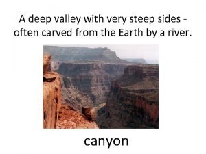
 A deep valley with steep sides of rock
 Irvine ranch water district process diagram
 Toledo city water district
 Contra costa toilet rebate
 Vance county water
 Irvine ranch water district
 Monterey peninsula water management district
