Chapter 8 Physical Views Component Diagrams Note A


 • 作產品元件(Work Product Component) • 執行元件(Execution Component)")


- Slides: 33
Chapter 8 系統元件與結構塑模 Physical Views
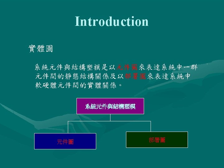
元件圖 – Component Diagrams 系統元件與結構塑模主要是以元件圖視覺化 的表達系統中一群實體元件與實體元件間的 靜態結構關係,及說明其建構之細節。 Note: A component diagram shows the dependencies among software components, including source code, binary code and executable components. Some components exist at compile time, some exist at link time, and some exist at run time; some exist at more than one time.
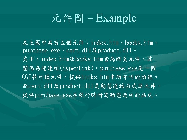
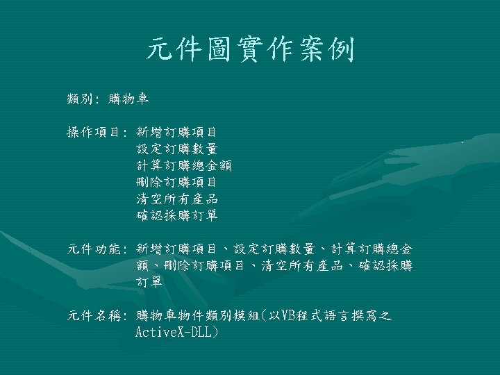
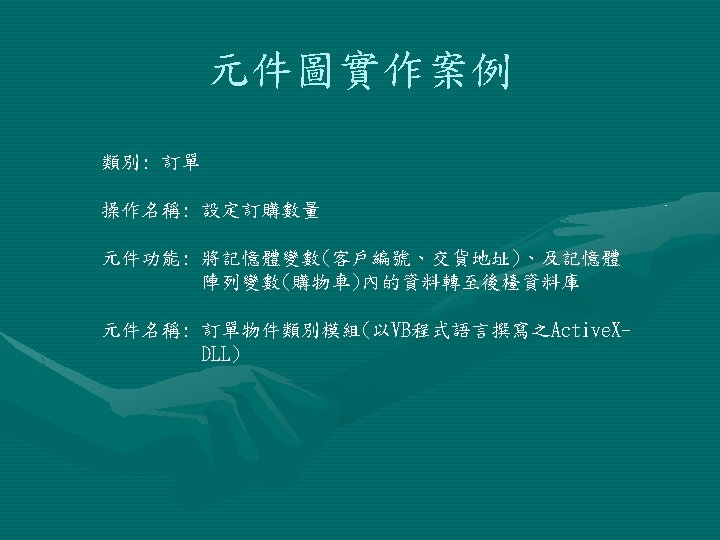
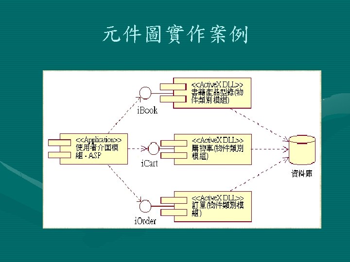
元件圖 – Example
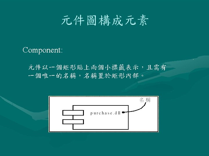
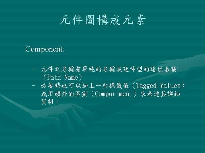
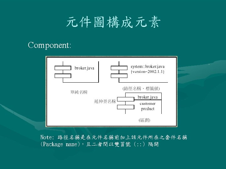
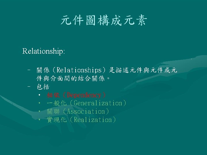
元件圖構成元素 Component: A component is a physical unit of implementation with well-defined interfaces that is intended to be used as a replaceable part of a system. Each component embodies the implementation of certain classes from the system design.
元件圖構成元素 Component: 三種主要元件: • 部署元件(Deployment Component) • 作產品元件(Work Product Component) • 執行元件(Execution Component)
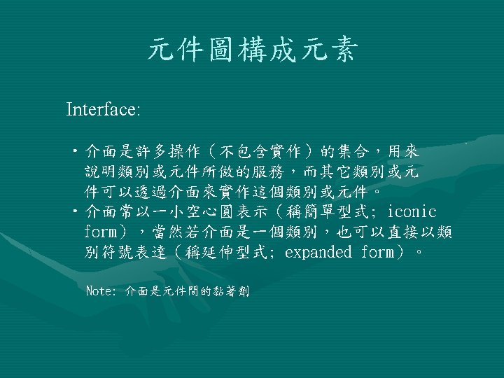
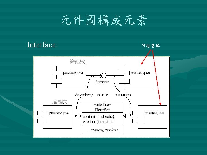
元件圖構成元素 Interface: An interface is a list of operations supported by a piece of software or hardware spell-check Dictionary synonyms Component Interface
元件圖構成元素 Relationship: Class Scheduler Class Registration Schedule Update Schedule Retrieval Registration GUI usage dependency
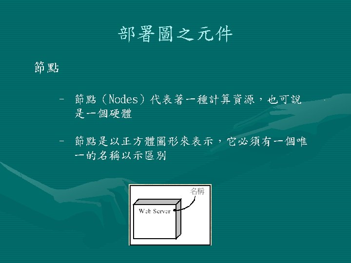
部署圖 – Deployment Diagram 系統元件與結構塑模主要是以部署圖視覺化的表達系統中 一群實體節點與實體節點間的靜態結構關係,及說明其建 構之細節。 Note: A Deployment diagram shows the configuration of run-time processing elements and the software components, processes, and objects. Software component instances represent run-time manifestations of code units. Components that do not exist as run-time entities do not appear on these diagrams. These components should be shown on component diagrams.
部署圖 - Example
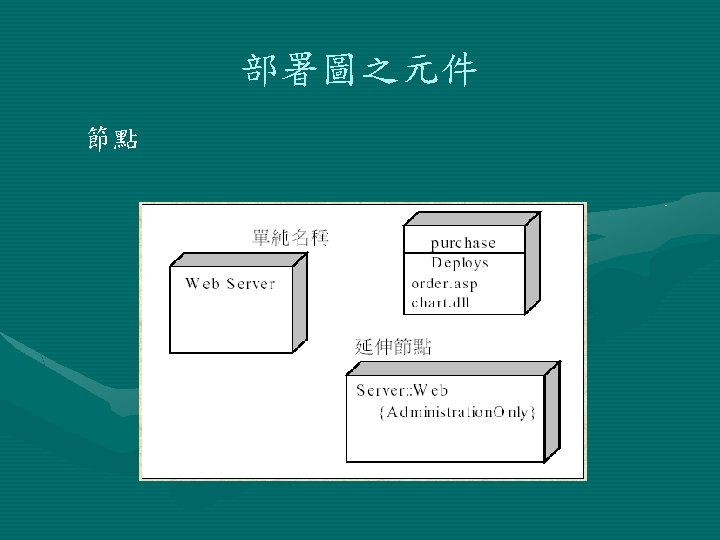
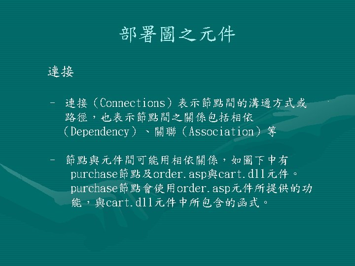
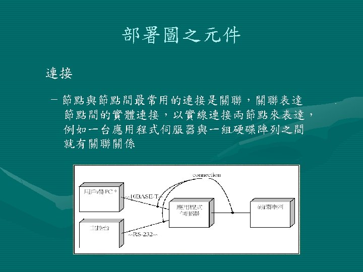
部署圖之元件 node 連接 Dependency connection purchase Order. asp Cart. dll components
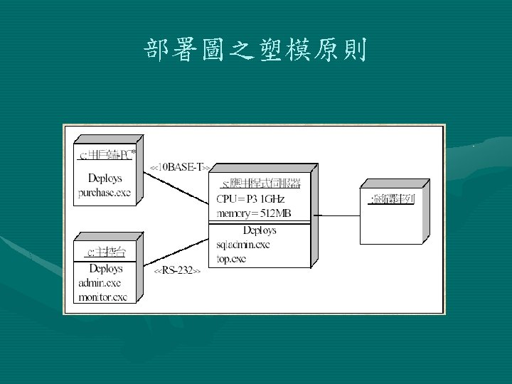
部署圖之塑模原則 • Identify the computational elements of your system’s deployment view and model each as a node • If these elements represent generic processors and devices, then stereotype them as such. If they are kinds of processors and devices that are part of the vocabulary of your domain, then specify an appropriate stereotype with an icon for each • As with class modeling, consider the attributes and operations that might apply to each node.