Chapter 4 Mardianaliza Othman 1 Transmission Lines A
- Slides: 17
Chapter 4 Mardianaliza Othman 1
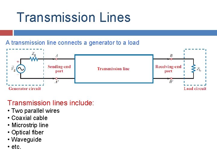
Transmission Lines A transmission line connects a generator to a load Transmission lines include: • Two parallel wires • Coaxial cable • Microstrip line • Optical fiber • Waveguide • etc.
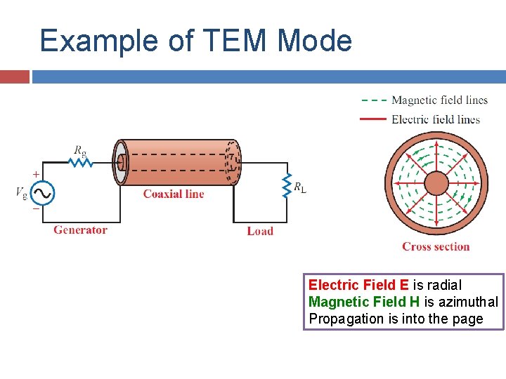
Example of TEM Mode Electric Field E is radial Magnetic Field H is azimuthal Propagation is into the page
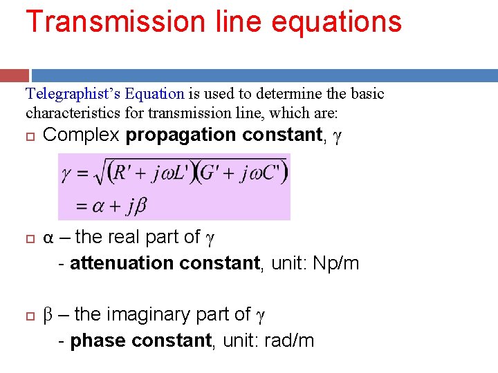
Transmission line equations Telegraphist’s Equation is used to determine the basic characteristics for transmission line, which are: Complex propagation constant, γ α – the real part of γ - attenuation constant, unit: Np/m β – the imaginary part of γ - phase constant, unit: rad/m
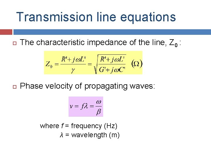
Transmission line equations The characteristic impedance of the line, Z 0 : Phase velocity of propagating waves: where f = frequency (Hz) λ = wavelength (m)
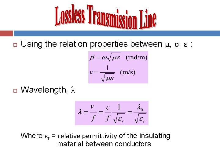
Using the relation properties between μ, σ, ε : Wavelength, λ Where εr = relative permittivity of the insulating material between conductors
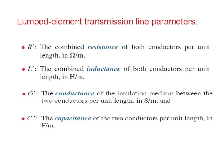
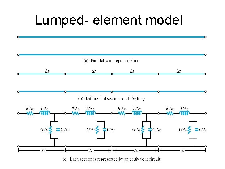
Lumped- element model • A transmission line is represented by a parallelwire configuration regardless of the specific shape of the line, i. e coaxial line, two-wire line. • Lumped element circuit model consists of four basic elements called ‘the transmission line parameters’ : R’ , L’ , G’ , C’.
Lumped-element transmission line parameters:
Lumped- element model
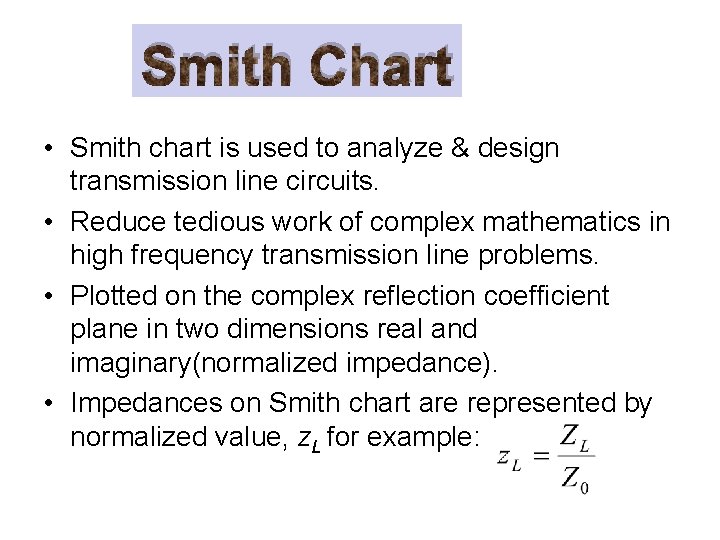
Smith Chart • Smith chart is used to analyze & design transmission line circuits. • Reduce tedious work of complex mathematics in high frequency transmission line problems. • Plotted on the complex reflection coefficient plane in two dimensions real and imaginary(normalized impedance). • Impedances on Smith chart are represented by normalized value, z. L for example:
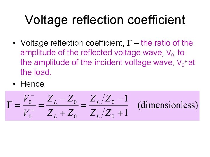
Voltage reflection coefficient • Voltage reflection coefficient, Γ – the ratio of the amplitude of the reflected voltage wave, V 0 - to the amplitude of the incident voltage wave, V 0+ at the load. • Hence,
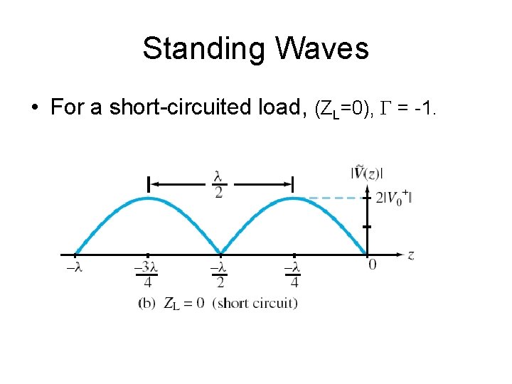
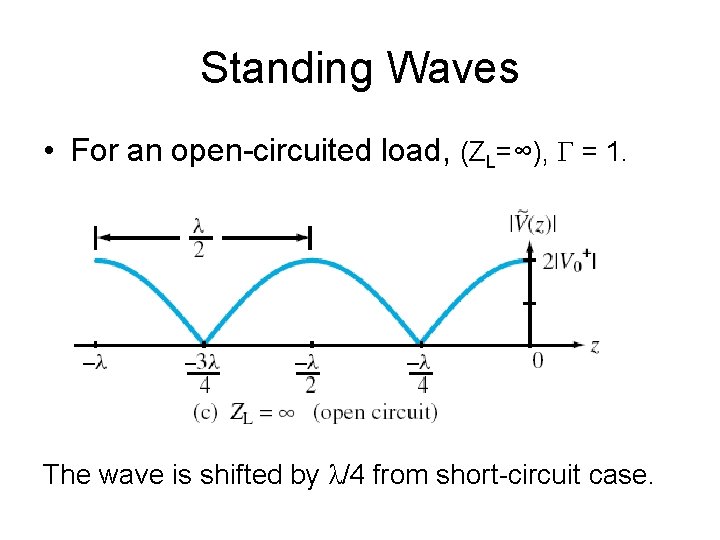
Standing Waves • Interference of the reflected wave and the incident wave along a transmission line creates a standing wave. • Constructive interference gives maximum value for standing wave pattern, while destructive interference gives minimum value. • The repetition period is λ for incident and reflected wave individually. • But, the repetition period for standing wave pattern is λ/2.
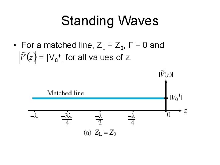
Standing Waves • For a matched line, ZL = Z 0, Γ = 0 and = |V 0+| for all values of z.
Standing Waves • For a short-circuited load, (ZL=0), Γ = -1.
Standing Waves • For an open-circuited load, (ZL=∞), Γ = 1. The wave is shifted by λ/4 from short-circuit case.
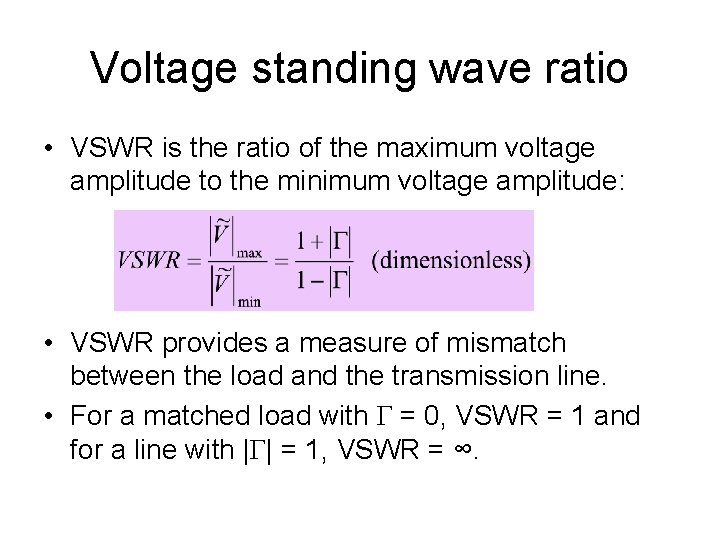
Voltage standing wave ratio • VSWR is the ratio of the maximum voltage amplitude to the minimum voltage amplitude: • VSWR provides a measure of mismatch between the load and the transmission line. • For a matched load with Γ = 0, VSWR = 1 and for a line with |Γ| = 1, VSWR = ∞.
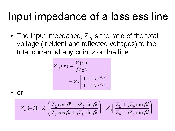
Input impedance of a lossless line • The input impedance, Zin is the ratio of the total voltage (incident and reflected voltages) to the total current at any point z on the line. • or