Chapter 4 Control Volume Analysis Using Energy continued
")


")
 Using Eq. 4. 12 in Eq.")
 In practice there may be several")


 ► ►If the kinetic energies of the flowing")


- Slides: 19
Chapter 4 Control Volume Analysis Using Energy (continued)
Learning Outcomes ►Distinguish between steady-state and transient analysis, ►Distinguishing between mass flow rate and volumetric flow rate. ►Apply mass and energy balances to control volumes. ►Develop appropriate engineering models to analyze nozzles, turbines, compressors, heat exchangers, throttling devices. ►Use property data in control volume analysis appropriately.
Mass Rate Balance time rate of change of mass contained within the control volume at time rate of flow of mass in across inlet i at time rate of flow of mass out across exit e at time t (Eq. 4. 2)
Determine the amount of water In tank after 1 hour
Energy Rate Balance time rate of change of the energy contained within the control volume at time t net rate at which energy is being transferred in by heat transfer at time t net rate at which energy is being transferred out by work at time t net rate of energy transfer into the control volume accompanying mass flow (Eq. 4. 9)
Evaluating Work for a Control Volume The expression for work is (Eq. 4. 12) where accounts for work associated with rotating shafts, displacement of the boundary, and electrical effects. ► is the flow work at exit e. ► ► is the flow work at inlet i.
Control Volume Energy Rate Balance (One-Dimensional Flow Form) Using Eq. 4. 12 in Eq. 4. 9 (Eq. 4. 13) For convenience substitute enthalpy, h = u + pv (Eq. 4. 14)
Control Volume Energy Rate Balance (One-Dimensional Flow Form) In practice there may be several locations on the boundary through which mass enters or exits. Multiple inlets and exits are accounted for by introducing summations: (Eq. 4. 15) Eq. 4. 15 is the accounting balance for the energy of the control volume.
Turbines ►Turbine: a device in which power is developed as a result of a gas or liquid passing through a set of blades attached to a shaft free to rotate.
Determine the Velocity At each exit duct where V is velocity v is specific volume
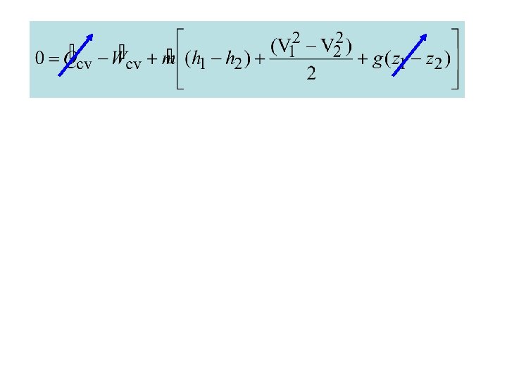
Turbine Modeling Eq. 4. 20 a ►If the change in kinetic energy of flowing matter is negligible, ½(V 12 – V 22) drops out. ►If the change in potential energy of flowing matter is negligible, g(z 1 – z 2) drops out. ►If the heat transfer with surroundings is negligible, drops out.
Heat Exchangers ►Direct contact: A mixing chamber in which hot and cold streams are mixed directly. ►Tube-within-a-tube counterflow: A gas or liquid stream is separated from another gas or liquid by a wall through which energy is conducted. Heat transfer occurs from the hot stream to the cold stream as the streams flow in opposite directions.
Heat Exchanger Modeling (Eq. 4. 18) ► ►If the kinetic energies of the flowing streams are negligible, (Vi 2/2) and (Ve 2/2) drop out. ►If the potential energies of the flowing streams are negligible, gzi and gze drop out. ►If the heat transfer with surroundings is negligible, drops out.
4 3