CEPC Superconducting RF System Design Jiyuan Zhai CEPCSPPC


![“Ultimate” CEPC Performance tt H W Z Beam Energy [Ge. V] 175 120 80](https://slidetodoc.com/presentation_image_h2/993b312a9e6246c8559e9aaba615b0fe/image-4.jpg "“Ultimate” CEPC Performance tt H W Z Beam Energy [Ge. V] 175 120 80")

 1. Common cavity for DR, RF sections NRF-DR-CC = 2")
 7. Detuning frequency Δf < 3 k. Hz (revolution frequency).")

 tt H W Z Loss factor / cell [V/p.")
 tt H W Z 5 2 1 1 Cavity")
 Heat load limited Margin for high voltage tt H")


![CEPC Main Ring SRF Parameters (50 MW per beam) [Jiyuan Zhai 20170112] 100 km,](https://slidetodoc.com/presentation_image_h2/993b312a9e6246c8559e9aaba615b0fe/image-15.jpg "CEPC Main Ring SRF Parameters (50 MW per beam) [Jiyuan Zhai 20170112] 100 km,")
![CEPC Main Ring SRF Parameters (reduced power) [Jiyuan Zhai 20170112] 100 km, 2 IPs,](https://slidetodoc.com/presentation_image_h2/993b312a9e6246c8559e9aaba615b0fe/image-16.jpg "CEPC Main Ring SRF Parameters (reduced power) [Jiyuan Zhai 20170112] 100 km, 2 IPs,")


 Low Power")

 ‐")


 113002")
 113002")


 Machine Top Parameters CEPC-WD 161123; FCC-V 3")
 WD 161123, Zhai 161130 H-HV")


 Number of IPs Energy")
 Pre-CDR H-high lumi.")
 Number of IPs")
 Number of IPs")
 Pre-CDR Number of IPs Energy (Ge. V)")
 CEPC 1. 3 GHz LCLS-II 1. 3 GHz XFEL 1. 3")
- Slides: 44
CEPC Superconducting RF System Design Jiyuan Zhai CEPC-SPPC Accelerator and Detector Simulation Design Study Meeting Jan. 14, 2017, IHEP
Outline • Ultimate machine performance • SRF limitations, scenarios and parameters ‐ boundary conditions (physics, operation, technology, cost) ‐ separately optimized SRF systems (tt, H, W, Z) ‐ SRF complex, staging and layout ‐ SRF parameters (50 MW and 30 MW) • Technical challenges ‐ R&D program ‐ opportunities for technological breakthroughs and cost reduction
Outline • Ultimate machine performance • SRF limitations, scenarios and parameters ‐ boundary conditions (physics, operation, technology, cost) ‐ separately optimized SRF systems (tt, H, W, Z) ‐ SRF complex, staging and layout ‐ SRF parameters (50 MW and 30 MW) • Technical challenges ‐ R&D program ‐ opportunities for technological breakthroughs and cost reduction
“Ultimate” CEPC Performance tt H W Z Beam Energy [Ge. V] 175 120 80 45. 5 Luminosity / IP [1034 cm-2 s-1] 0. 6 5. 4 12 70 SR power / beam [MW] 50 RF voltage [GV] 8. 9 2 0. 63 0. 11 Beam current / beam [m. A] 6. 6 30 152 1450 Bunch charge [n. C] 22. 6 18 16. 8 7. 4 Bunch length [mm] 2. 7 2. 9 3. 9 4 Bunches / beam 98 555 3000 65716 1704 301 56 3 Bunch spacing [ns] β*y [mm] SR loss / turn [GV] 2 7. 55 CW RF voltage, beam current, instability … most challenging in history ~ 27 GV CW SRF cavity for DR including booster twice the current in cavity except DR very short bunch in storage ring two RF buckets 1 1. 67 0. 33 0. 034 Machine parameters from Dou Wang (W parameters extrapolated to 50 MW SR power per beam). 100 km, 2 IPs, 30 mrad crossing angle with crab waist, 650 MHz RF for the main ring, double-ring with common RF cavity and half ring filled. little damping
Outline • Ultimate machine performance • SRF limitations, scenarios and parameters ‐ boundary conditions (physics, operation, technology, cost) ‐ separately optimized SRF systems (tt, H, W, Z) ‐ SRF complex, staging and layout ‐ SRF parameters (50 MW and 30 MW) • Technical challenges ‐ R&D program ‐ opportunities for technological breakthroughs and cost reduction
SRF Boundary Conditions (1) 1. Common cavity for DR, RF sections NRF-DR-CC = 2 , half bucket filled 2. Cavity operation gradient Eacc < 20 MV/m (cryo heat load, technology) 3. HOM power / cavity PHOM < 2 k. W (HOM coupler; for HL-Z HOM absorber @ RT < 15 k. W) 4. Input power / cavity PCPL< 300 k. W (one coupler per cavity, variable input coupler, otherwise large extra power of mismatching; for HL-Z: 400 + 400 k. W) 5. Cavity operation Q 0 < 2 E 10 at 2 K (magnetic shielding and field emission limit, long-term cavity performance degradation) 6. Cryogenic heat load of total cavity wall loss at 4. 5 K eq. WCAV < 30 k. W (for tt < 80 k. W)
SRF Boundary Conditions (2) 7. Detuning frequency Δf < 3 k. Hz (revolution frequency). For HL-W&Z, use direct loop and comb filter loop feedback to cure the fundamental mode instability (PEP-II, LHC), bunch by bunch may not work 8. Max phase shift of bunch train Δφmax (lifetime, luminosity, instability) 9. Cryomodule length LCM < 12 m 10. Common cavity for (A)PDR, RF sections NRF-PDR-CC = 8, 2 half sections each 11. Total bunch train length per beam Tt /T 0 < 6 % of the circumference ((A)PDR)
Performance Limitations • Detector: If the detector set limitation to the bunch spacing, we need to reduce the bunch number, thus the beam current and luminosity (assume beam-beam limited), especially for the cases of partial double ring (95 % buckets loss) and double ring with common RF cavity (50 % buckets loss). • Z-pole: cavity impedance of the high current and small damping is the most concern. Smallest number of cavities to provide 2 x 50 MW power to the beam. Very high input coupler power, consider two couplers per cavity. Huge HOM power and HOM absorber: Super. KEKB / BEPCII type cryomodule (one 1 -cell cavity per module). Parasitic loss. • tt: high RF voltage (both Main Ring and Booster) requires both high gradient and high Q, especially for CW operation. Must push SRF frontier. • H & W : HOM coupler power handling in multi-cavity cryomoudle. High Q.
Separately Optimized SRF Systems (1) tt H W Z Loss factor / cell [V/p. C] 0. 36 0. 34 0. 28 0. 27 HOM power / cell [k. W] 0. 1 0. 4 1. 4 5. 8 HOM power limit / cavity [k. W] 2 2 2 15 Input power limit / cavity [k. W] 300 300 800 Cavity gradient limit [MV/m] 20 20 16 16 Effective length / cell [m] 0. 23 Voltage limit / cell [MV] 4. 6 3. 68 R/Q per cell [Ω] 103 103 Min cavity number (input power) 333 333 125 Min total cell number (gradient) 1935 435 171 30 Max cell number / cavity (HOM power) 18 5 1 2 Min cavity number (gradient) 387 217 171 30 Min cavity number (input power + gradient) 387 333 125 Super. KEKB/ BEPCII type cryomodule 2 input couplers per cavity
Separately Optimized SRF Systems (2) tt H W Z 5 2 1 1 Cavity number 388 334 126 Gradient [MV/m] 19. 9 13. 0 8. 2 3. 8 Cavity voltage [MV] 22. 9 6. 0 1. 9 0. 9 Input power / cavity [k. W] 258 299 794 HOM power / cavity [k. W] 0. 5 0. 7 1. 4 5. 8 Cavity number / cryomodule 4 6 8 1 Cryomodule number 97 56 42 126 Cryomodule length [m] 10 10 8 4 Half FODO cell length in RF section [m] 50 50 Number of modules in a half FODO cell 4 4 5 10 606 348 209 315 Cost per cavity / M CNY 4 3. 5 3. 4 4 Main Ring SRF cost / 100 M CNY 16 12 11 5 Cell number / cavity Half RF section length [m] Less cell for impedance and beam loading Margin for high voltage
Separately Optimized SRF Systems (3) Heat load limited Margin for high voltage tt H W Z 2 E+10 1 E+10 8 E+09 5 E+09 Wall loss / cavity @ 2 K [W] 51 17 4 1 Total wall loss @ 4. 5 K eq. [k. W] 70 21 5 0. 7 Total installed cryo @ 4. 5 K eq. [k. W] 120 70 55 20? 4. 0 E+06 5. 8 E+05 1. 2 E+05 9. 3 E+03 Optimal detuning [k. Hz] 0. 05 0. 37 4. 58 107. 25 Cavity bandwidth [k. Hz] 0. 2 1. 1 5. 6 69. 7 Cavity time constant [μs] 1941 285 56 5 Cavity stored energy [J] 250 43 8 2 2. 4 % 17 % 136 % 2795 % 2. 6 17. 6 decelerate Q 0 at operating gradient Optimal QL Max relative voltage drop for 4+4 APDR [MV] Max bunch train phase shift for 4+4 APDR [deg] ttbar SRF and cryogenic systems not much bigger than those of Pre-CDR Higgs
SRF Complex • Impossible to have four separate SRF systems or a single common system for the wide parameters range • A staged SRF complex is needed with prioritization and compromise (physcis, operation, technology, cost) • For SRF conceptual design phase, we assume: ‐ highest priority: Higgs ‐ second priority: Z-pole ‐ third priority: ttbar and WW threshold
SRF Configuration and Staging Preliminary proposal: • SRF system optimized for H (2 -cell cavity) ‐ • Same (all) 2 -cell cavities for W ‐ • but lower luminosity, HOM limited; same RF configuration with H Separate high current 1 -cell cavity for Z ‐ • highest luminosity but lower luminosity, input coupler power and cost limited Extending high gradient 5 -cell cavity for tt in the future ‐ including booster cavity extension, double the SRF and cryogenic investment RF power source configuration and power distribution for Z and tt to be solved.
SRF Complex Layout SRF Cavity, Cryogenics, RF Power Source and Distribution Complex RF station length (left half) H&W : 350 m Z: 315 m tt (extend): 200 + 200 m Ring layout based on Feng Su, Dec 15, 2016
CEPC Main Ring SRF Parameters (50 MW per beam) [Jiyuan Zhai 20170112] 100 km, 2 IPs, , 650 MHz, doublering with common RF cavity tt (extend H) H (optimized) W (share H) Z (separate) Luminosity / IP [10 34 cm-2 s-1] 0. 6 5. 4 (β*y =1 mm) 12 70 SR power / beam [MW] 50 RF voltage [GV] 8. 9 2 0. 63 0. 11 Beam current / beam [m. A] 6. 6 30 152 1450 Bunches / beam 98 555 3000 65716 Cell number / cavity 5 2 1 254 add (388) 334 126 Cavity number Gradient [MV/m] 19. 9 13. 0 4. 1 3. 8 Input power / cavity [k. W] 258 299 794 HOM power / cavity [k. W] 0. 5 0. 7 2. 9 5. 8 Cryomodule number 97 Q 0 at operating gradient 56 126 2 E+10 1 E+10 8 E+09 5 E+09 70 21 3 0. 7 4. 0 E+06 5. 8 E+05 5. 8 E+04 9. 3 E+03 Optimal detuning [k. Hz] 0. 05 0. 37 9. 16 107. 25 Relative optimal QL (to H) 6. 8 1. 0 0. 1 (0. 02) Staging input power [k. W] 258 103 / / Extra power due to mismatch / 124% 204% / Main ring SRF cost [BCNY] 1 (1. 6) 1. 2 0. 5 2. 7 BCNY Main Ring SRF HWZ cost 1. 7 BCNY Total wall loss @ 4. 5 K eq. [k. W] Optimal QL Main Ring SRF total cost
CEPC Main Ring SRF Parameters (reduced power) [Jiyuan Zhai 20170112] 100 km, 2 IPs, , 650 MHz, double-ring with common RF cavity tt (extend H) H (optimized) W (share H) Z (separate) 0. 36 3 (β*y =1 7 14 28 42 SR power / beam [MW] 30 30 30 10 20 30 RF voltage [GV] 8. 9 2 0. 63 0. 11 Beam current / beam [m. A] 4 18 91. 2 290 580 870 Cell number / cavity 5 1 1 Luminosity / IP [10 34 cm-2 s-1] Cavity number mm) 2 274 (388) 284 68 75 75 Gradient [MV/m] 19. 9 15. 3 4. 8 3. 5 6. 4 Input power / cavity [k. W] 155 211 294 533 800 HOM power / cavity [k. W] 0. 3 0. 4 1. 7 2. 3 3. 5 Cryomodule number 97 47 47 11 75 75 2 E+10 1 E+10 8 E+09 5 E+09 70 24 3 0. 6 1. 1 6. 6 E+06 1. 1 E+05 4. 3 E+04 3. 9 E+04 2. 6 E+04 Optimal detuning [k. Hz] 0. 03 0. 19 4. 67 23. 15 25. 54 38. 31 Relative optimal Qe (to H) 5. 8 1. 0 0. 1 0. 04 0. 03 0. 02 Staging input power [k. W] 155 62 204% 611% 0. 3 Q 0 at operating gradient Total wall loss @ 4. 5 K eq. [k. W] Optimal QL Extra power due to mismatch [k. W] Main Ring SRF cost [BCNY] Main Ring SRF total cost [BCNY] 99% 1. 1 (1. 6) 1 2. 1
Extra Power due to Mismatch where, q is the relative change to optimal QL, ε is the change of detuning to optimal detuning over half bandwidth. • Only one mode can achieve 100 % RF to beam power efficiency at its nominal design. • More power needed for other modes. Coupler capacity, power efficiency, and RF distribution problem. Under-coupling not good for stability. Variable Coupler (cost, cleanness). 17
Transient Beam Loading of PDR • Phase shift caused by beam loading ‐ • A bunch extracts cavity stored energy when passing through, and power source will recover the cavity voltage when the next bunch comes. When the bunch spacing is much smaller, cavity stored energy and voltage will drop continuously due to lack of power. The latter bunch will move towards voltage peak by auto-phasing, resulting in less longitudinal focusing, smaller energy acceptance, lifetime and luminosity, and possible other dynamical problem. Small phase shift can be estimated by: Correction methods 1. Increase cavity stored energy (less cell number, higher RF voltage, low RF freq) 2. More uniform distribution (increase bunch train number or length) 3. Pulsed power (power source hardware limit and low RF-to-beam efficiency) 4. Beat cavity (small frequency shift of part of RF sources and cavities, beating) Refer to Jiyuan Zhai’s talk in the CEPC-SPPC Workshop, Apr. and Sept. 2016
Phase Shift and Beat Cavity Machine Parameter: H wangdou 20160918/23(Circumference 61 km) Low Power H High Lumi W Z Z 1 -cell Bunch charge (n. C) 32 32 18. 6 12. 5 Bunch number (one beam) 70 107 400 1100 152. 3 98. 5 26. 2 9. 2 Cavity voltage (MV) 7. 4 7. 3 3. 9 3. 7 Synchrotron phase (deg) 123 122 128 146 11 % 18 % 72 % 140 % 70 % PDR 1+1 max phase shift (deg) 12 19 67 / 49 PDR 3 rd order beat cavity# (29 k. Hz) 33 51 83 28 14 3% 4% 18 % 35 % 18 % APDR 4+4 max phase shift (deg) 3 4. 8 16. 7 24. 2 12. 1 APDR 2 nd order beat cavity# (79 k. Hz) 10 16 27 9 4 Bunch spacing (ns) [bunch train length < 3. 2 km] PDR 1+1 max voltage drop APDR 4+4 max voltage drop
Outline • Ultimate machine performance • SRF limitations, scenarios and parameters ‐ boundary conditions (physics, operation, technology, cost) ‐ separately optimized SRF systems (tt, H, W, Z) ‐ SRF complex, staging and layout ‐ SRF parameters (50 MW and 30 MW) • Technical challenges ‐ R&D program ‐ opportunities for technological breakthroughs and cost reduction
R&D Program • MOST and other funds for CEPC SRF R&D (2016 -2020) ‐ ‐ key technology (high Q cavity, Nitrogen-doping, electro-polishing) component design, fabrication and test (NEW Technology) • ‐ integrated demonstration • • high power variable input coupler, high power HOM coupler and absorber, high Q cavity with helium vessel and good magnetic shield, robust tuner, cryomodule of low magnetic field and fast cool down, ultra-clean RF-shielded bellow … one Main Ring module (two 650 MHz 2 -cell cavities) and one Booster module (one CW 1. 3 GHz 9 -cell TESLA cavity) assembly and beam test Large SRF infrastructures to be built in Huairou Science Park (20172019) ‐ ‐ SRF lab: 4500 m 2 + cryoplant SRF facilities: material study, cavity processing, tuning, assembly, vertical testing, defects diagnostics and repairing tool, horizontal testing and beam test
CEPC 650 MHz SRF Cryomodule
CEPC SRF Technology R&D Prototype design and fabrication in 2017 -2018 650 MHz 2 -cell cavity & tuner 5 -cell cavity Q > 2 E 10 @ 20 MV/m 650 MHz variable coupler 300 k. W HOM coupler 1 k. W HOM absorber 5 k. W 1. 3 GHz TESLA cavity (high Q high gradient study) 650 MHz & 1. 3 GHz cryomodule < 5 W @ 2 K 1. 3 GHz variable coupler 20 k. W
Opportunities for Technological Breakthroughs and Cost Reduction High Gradient and High Q • N-infusion (ILC ongoing R&D program aiming for 30 % cost reduction, could reduce CEPC tt MR and Booster CW cavity cost as well as other operation modes; but need extremely clean assembly, vacuum and magnetic environment) • Nb 3 Sn (~ 100 nm thin film Nb to have Bean-Livingstone and SS boundary barrier against penetration of vortex) • 铁基超导 (SIS thin film) Nb/Cu Very high power input coupler (CW 0. 5 -1 MW) …
Superconductors A-M. Valente-Feliciano. Supercond. Sci. Technol. 29 (2016) 113002
Material for Superconducting RF Cavity 1000 A-M. Valente-Feliciano. Supercond. Sci. Technol. 29 (2016) 113002
SRF Summary of Main Ring Types Luminosity SRF Operation SRF Technology SRF Cost Single Ring (SR) Partial Double Ring (PDR) Advanced Partial Double Ring (APDR) Double Ring with Common Cavity (DRcc) Double Ring (DR) HL-H too many bunches for pretzel; Z too low; Showstopper bunch spacing limited by detector; Z low Problematic tt, H, W same with DR; highest Z lower than DR BEST H high impedance, instability beam current severely limited by transient beam loading Showstopper beam loading better than PDR, very serious for HL -W & Z Problematic no beam loading problem; double current, instability; half bunch spacing for feedback BEST HOM power Problematic pulsed HOM power; LLRF control; beat cavity? Double cavity input and HOM power; very high input power for HL-Z Not good BEST H cost higher than DRcc similar to DRcc; beat cavity will add cost BEST especially for tt; save cryogenics twice SRF and cryogenic cost (4 BCNY) of DRcc Problematic
Summary • Superconducting RF system is crucial to explore the full potential and reach the ultimate performance of CEPC. We are actually designing four most difficult machines in the history of (SRF) accelerator. • A staged SRF complex is proposed with priority. Parameters given for two SR power scenarios. Different technical solutions, risks, costs and layout for different luminosity requirement and main ring type. Double ring with common cavity is preferred. • Remained design issues: high luminosity Z-pole operation, high power wide range variable coupler, HOM coupler, Booster SRF design, transient beam loading and compensation… • Frontier SRF technologies are demanding to control the overall cost. SRF R&D and new infrastructures to push the limit and affect the final design.
Backup
CEPC 100 km & FCC-ee (w/o tt) Machine Top Parameters CEPC-WD 161123; FCC-V 3 C-H-HV Luminosity / IP [1034 cm-2 s-1] C-H-LP C-H-HL C-W C-Z-LL C-Z-HL F-H F-W F-Z-HL F-Z-LL 3 4. 5 1. 2 70 5 19 207 90 120 80 2 Beam energy [Ge. V] 120 80 45. 5 SR power / beam [MW] 33 50 18. 3 0. 84 50 Beam current / beam [m. A] 20 30 56 24 1450 30 152 Bunches / beam Bunch spacing [ns] APDR / DR 45. 6 50 1450 1006 425 644 1100 65716 780 5260 30180 91500 20 / 166 47 / 391 31 / 257 17 / 151 NA / 1. 5 400 50 7. 5 2. 5 Bunch population [1011] 0. 41 0. 97 1. 05 0. 46 0. 8 0. 6 1 0. 33 Horizontal emittance εx [nm] Vertical emittance εy [pm] 0. 88 2. 7 1. 56 4. 7 2. 68 8 0. 93 4. 9 0. 61 1. 2 0. 26 1 0. 2 1 0. 09 1 Momentum compaction [10 -5] 0. 87 1. 3 3. 1 3. 3 Betatron function at IP βx* [m] βy* [mm] 0. 08 2 0. 14 2 0. 1 1 0. 12 1 1 2 0. 5 1 1 2 Horizontal beam size σx* [μm] σy* [nm] 8. 46 73 15 97 16. 4 90 10. 5 70 25 49 16 45 10 32 9. 5 45 Energy spread [%] SR Total 0. 1 1. 95 0. 1 1. 5 0. 07 ? 0. 04 ? 0. 10 0. 12 0. 07 0. 10 0. 04 0. 22 0. 04 0. 09 Bunch length [mm] SR Total 1. 53 1. 63 2. 72 2. 9 3. 8 3. 93 4. 0 2. 4 2. 0 3. 1 1. 2 6. 7 1. 6 3. 8 0. 33 0. 03 1. 67 0. 33 0. 03 0. 63 0. 11 3 0. 8 0. 4 0. 2 Energy loss / turn [Ge. V] Total RF voltage [GV] 1. 67 3. 56 2. 22 RF frequency [MHz] Energy acceptance / RF [%] 0. 7 650 400 1. 95 / 6 1. 5 / 2. 2 1 / 1. 5 1 / 1. 1 2/7 2 / 5. 5 1 / 7. 2 1 / 4. 7 Hourglass factor 0. 98 0. 95 0. 84 0. 91 0. 92 0. 95 0. 92 0. 98 Beam-beam parameter ξx ξy 0. 009 0. 083 0. 013 0. 083 0. 008 0. 055 0. 08 0. 14 0. 07 0. 16 0. 025 0. 16 0. 05 0. 13 52 25? 144 67 90 94 185 Lifetime [min] BS or BB circumference 100 km, bending radius 11 km, crossing angle 30 mrad, two IPs 0. 008 0. 054 238
CEPC 100 km SRF Parameters (DR and 4+4 APDR) WD 161123, Zhai 161130 H-HV H-LP H-HL W Z-LL Z-HL Luminosity [1034 cm-2 s-1] 2 3 4. 5 1. 2 70 SR power / beam [MW] 33 50 18. 3 0. 84 50 Beam current / beam [m. A] 20 30 56 24 1450 Bunches / beam 1006 425 644 1100 65716 Bunch spacing [ns] APDR / DR 20 / 166 47 / 391 31 / 257 17 / 151 NA / 1. 5 Bunch charge / length [n. C / mm] 6. 6 / 1. 6 15. 5 / 2. 9 16. 8 / 3. 9 7. 4 / 4. 0 RF voltage [GV] (w/ para. loss) 3. 57 2. 24 0. 65 0. 12 Synchrotron phase [deg] (from low zero) 152. 1 131. 3 148. 5 161. 7 Number of cells in a cavity 2 1 384 240 384 128 16 64 64 / 6 48 / 5 64 / 6 32 / 4 16 / 1 64 / 1 Cavity operating gradient [MV/m] (< 20) 20 20 12. 6 11. 0 16. 7 8. 4 Q 0 at operating gradient @ 2 K (< 2 E 10) 2. 0 E+10 1. 2 E+10 8. 0 E+09 Input power / cavity (match) [k. W] (< 300) 173 277 263 295 117 1757 HOM power / cavity [k. W] (< 1) 0. 25 0. 42 0. 63 1. 04 0. 20 5. 84 Cavity wall loss @ 4. 5 K eq. [k. W] (< 30) 28. 7 30. 0 28. 2 7. 1 2. 1 1. 0 2. 4 E+06 1. 5 E+06 6. 3 E+05 4. 3 E+05 2. 5 E+06 2. 1 E+04 0. 3 / 1196 0. 4 / 747 1. 0 / 308 1. 5 / 209 0. 3 / 1207 31. 4 / 10 Detuning frequency [k. Hz] (< 3) -0. 25 -0. 19 -0. 45 -1. 24 -0. 40 -47. 62 Cavity stored energy [J] 103. 2 103. 4 40. 5 30. 8 70. 8 8. 9 Max voltage drop (4 trains / beam) [%] 7 7 16 34 10 decelerate Max phase shift (4 trains / beam) [deg] 4. 3 5. 8 14. 1 23. 0 6. 0 decelerate Number of 650 MHz cavities Number of cryomodules / cavity per module QL (match) Cavity bandwidth / fill time [k. Hz / μs]
Higgs-HV Cell Number Comparison WD 161123, Zhai 161130 H-HV 2 -cell H-HV 3 -cell Luminosity [1034 cm-2 s-1] 2 SR power / beam [MW] 33 RF voltage [GV] (w/ para. loss) Number of cells in a cavity H-HV 4 -cell H-HV 5 -cell 3. 57 2 3 4 5 384 320 256 64 / 5 64 / 4 Cavity operating gradient [MV/m] (< 20) 20 16. 2 15. 1 12. 1 Q 0 at operating gradient @ 2 K (< 2 E 10) 2. 0 E+10 1. 5 E+10 1. 2 E+10 Input power / cavity (match) [k. W] (< 300) 173 207 259 HOM power / cavity [k. W] (< 1) 0. 25 0. 38 0. 51 0. 63 Cavity wall loss @ 4. 5 K eq. [k. W] (< 30) 28. 7 30. 7 28. 8 2. 4 E+06 2. 0 E+06 1. 8 E+06 1. 5 E+06 0. 3 / 1196 0. 3 / 957 0. 4 / 897 0. 4 / 718 Detuning frequency [k. Hz] (< 3) -0. 25 -0. 31 -0. 33 -0. 42 Cavity stored energy [J] 103. 2 99. 2 116. 2 93. 1 Max voltage drop (4 trains / beam) [%] 7 8 9 11 Max phase shift (4 trains / beam) [deg] 4. 3 5. 4 5. 8 7. 2 Number of 650 MHz cavities Number of cryomodules / cavity per module QL (match) Cavity bandwidth / fill time [k. Hz / μs]
Higgs-LP Cell Number Comparison WD 161123, Zhai 161130 H-LP 2 -cell H-LP 3 -cell Luminosity [1034 cm-2 s-1] 2 SR power / beam [MW] 33 RF voltage [GV] (w/ para. loss) Number of cells in a cavity H-LP 4 -cell H-LP 5 -cell 4 5 2. 24 2 3 Number of 650 MHz cavities 240 Number of cryomodules / cavity per module 48 / 5 Cavity operating gradient [MV/m] (< 20) 20. 2 13. 5 10. 1 8. 1 Q 0 at operating gradient @ 2 K (< 2 E 10) 1. 2 E+10 8. 0 E+09 6. 0 E+09 5. 0 E+09 277 Input power / cavity (match) [k. W] (< 300) HOM power / cavity [k. W] (< 1) 0. 42 0. 63 0. 83 1. 04 Cavity wall loss @ 4. 5 K eq. [k. W] (< 30) 30. 0 30. 1 28. 9 QL (match) 1. 5 E+06 1. 0 E+06 7. 6 E+05 6. 1 E+05 Cavity bandwidth / fill time [k. Hz / μs] 0. 4 / 747 0. 6 / 498 0. 9 / 374 1. 1 / 299 Detuning frequency [k. Hz] (< 3) -0. 19 -0. 28 -0. 37 -0. 47 Cavity stored energy [J] 103. 4 69. 0 51. 9 41. 6 Max voltage drop (4 trains / beam) [%] 7 10 13 17 Max phase shift (4 trains / beam) [deg] 5. 8 8. 7 11. 6 14. 5
Higgs-HL Cell Number Comparison WD 161123, Zhai 161130 H-HL 2 -cell H-HL 3 -cell Luminosity [1034 cm-2 s-1] 3 SR power / beam [MW] 50 RF voltage [GV] (w/ para. loss) Number of cells in a cavity H-HL 4 -cell H-HL 5 -cell 4 5 2. 24 2 3 Number of 650 MHz cavities 384 Number of cryomodules / cavity per module 64 / 6 Cavity operating gradient [MV/m] (< 20) 12. 6 8. 4 6. 3 5. 1 Q 0 at operating gradient @ 2 K (< 2 E 10) 8. 0 E+09 5. 0 E+09 4. 0 E+09 3. 0 E+09 263 Input power / cavity (match) [k. W] (< 300) HOM power / cavity [k. W] (< 1) 0. 63 0. 95 1. 26 1. 58 Cavity wall loss @ 4. 5 K eq. [k. W] (< 30) 28. 2 30. 1 28. 3 30. 3 6. 3 E+05 4. 2 E+05 3. 2 E+05 2. 5 E+05 1 / 308 1. 5 / 206 2. 1 / 155 2. 6 / 124 Detuning frequency [k. Hz] (< 3) -0. 45 -0. 68 -0. 90 -1. 13 Cavity stored energy [J] 40. 5 27. 1 20. 4 16. 3 Max voltage drop (4 trains / beam) [%] 16 24 32 40 Max phase shift (4 trains / beam) [deg] 14 21 28 35 QL (match) Cavity bandwidth / fill time [k. Hz / μs]
W Cell Number Comparison WD 161123, Zhai 161130 W 2 -cell W 3 -cell Luminosity [1034 cm-2 s-1] 4. 5 SR power / beam [MW] 18. 3 Total RF voltage [GV] (w/ para. loss) 0. 65 Number of cells in a cavity 2 3 Number of 650 MHz cavities W 4 -cell W 5 -cell 4 5 128 Number of cryomodules / cavity per module 32 / 4 Cavity operating gradient [MV/m] (< 20) 11. 0 7. 4 5. 5 4. 4 Q 0 at operating gradient @ 2 K (< 2 E 10) 8. 0 E+09 295 Input power / cavity (match) [k. W] (< 300) HOM power / cavity [k. W] (< 1) 1. 0 1. 6 2. 1 2. 6 Cavity wall loss @ 4. 5 K eq. [k. W] (< 30) 7. 1 4. 8 3. 6 2. 9 QL (match) 4. 3 E+05 2. 9 E+05 2. 1 E+05 1. 7 E+05 Cavity bandwidth / fill time [k. Hz / μs] 1. 5 / 209 2. 3 / 140 3 / 105 3. 8 / 84 Detuning frequency [k. Hz] (< 3) -1. 24 -1. 86 -2. 47 -3. 08 Cavity stored energy [J] 30. 8 20. 6 15. 5 12. 5 Max voltage drop (4 trains / beam) [%] 23 34 46 57 Max phase shift (4 trains / beam) [deg] 34 51 68 85
FCC-ee baseline
Erk Jensen, FCC Week 2016 FCC-ee SRF Parameters
parameter for CEPC partial double ring (wangdou 20161109 -61 km) Number of IPs Energy (Ge. V) Circumference (km) SR loss/turn (Ge. V) Half crossing angle (mrad) Piwinski angle Ne/bunch (1011) Bunch number Beam current (m. A) SR power /beam (MW) Bending radius (km) Momentum compaction (10 -5) IP x/y (m) Emittance x/y (nm) Transverse IP (um) x/IP y/IP VRF (GV) f RF (MHz) Nature z (mm) Total z (mm) HOM power/cavity (kw) Energy spread (%) Energy acceptance by RF (%) n Life time due to beamstrahlung_cal (minute) F (hour glass) Pre-CDR H-high lumi. H-low power 2 120 54 3. 1 0 0 3. 79 50 16. 6 51. 7 6. 1 3. 4 0. 8/0. 0012 6. 12/0. 018 69. 97/0. 15 0. 118 0. 083 6. 87 650 2. 14 2. 65 3. 6 0. 13 2 6 2 120 61 2. 96 15 1. 88 2. 0 107 16. 9 50 6. 2 1. 48 0. 272/0. 0013 2. 05/0. 0062 23. 7/0. 09 0. 041 0. 11 3. 48 650 2. 7 2. 95 0. 74 0. 13 2 2. 3 0. 23 47 0. 68 W Z Z-5 cell 2 120 61 2. 96 15 1. 84 1. 98 70 11. 0 32. 5 6. 2 1. 48 0. 275 /0. 0013 2. 05 /0. 0062 23. 7/0. 09 0. 042 0. 11 3. 51 650 2. 7 2. 9 0. 48 0. 13 2 2. 4 2 80 61 0. 58 15 4. 11 0. 85 400 26. 8 15. 7 6. 2 1. 48 0. 16/0. 001 0. 93/0. 003 12. 2/0. 056 0. 0145 0. 084 0. 7 650 3. 23 3. 35 0. 47 0. 087 2 45. 5 61 0. 061 15 5. 86 0. 6 1100 52. 0 3. 2 6. 2 3. 1 0. 12/0. 001 0. 87/0. 0046 10. 2/0. 068 0. 0098 0. 073 0. 12 650 3. 9 4. 0 0. 59 0. 05 2 45. 5 61 0. 061 15 5. 87 0. 6 700 33. 1 2. 0 6. 2 3. 1 0. 12/0. 001 0. 87/0. 0046 10. 2/0. 068 0. 0098 0. 073 0. 12 650 3. 9 4. 0 0. 93 0. 05 1. 3 1. 1 0. 35 37 0. 34 37 0. 28 0. 24 0. 82 0. 89 0. 9238
parameters for CEPC double ring (wangdou 20161202 -100 km_2 mm y) Pre-CDR H-high lumi. Number of IPs Energy (Ge. V) Circumference (km) SR loss/turn (Ge. V) Half crossing angle (mrad) Piwinski angle Ne/bunch (1011) Bunch number Beam current (m. A) SR power /beam (MW) Bending radius (km) Momentum compaction (10 -5) IP x/y (m) Emittance x/y (nm) Transverse IP (um) x/ y/IP RF Phase (degree) VRF (GV) f RF (MHz) (harmonic) Nature z (mm) Total z (mm) HOM power/cavity (kw) Energy spread (%) Energy acceptance by RF (%) n Life time due to beamstrahlung_cal (minute) F (hour glass) L /IP (1034 cm-2 s-1) H-low power W Z 2 120 54 3. 1 0 0 3. 79 50 16. 6 51. 7 6. 1 3. 4 0. 8/0. 0012 6. 12/0. 018 69. 97/0. 15 0. 118/0. 083 153. 0 6. 87 650 2. 14 2. 65 3. 6 (5 cell) 0. 13 2 6 0. 23 47 2 120 100 1. 67 15 2. 9 0. 97 644 29. 97 50 11 1. 3 0. 144 /0. 002 1. 56/0. 0047 15/0. 097 0. 0126/0. 083 131. 2 2. 22 650 (217800) 2. 72 2. 9 0. 64 (2 cell) 0. 098 1. 5 2. 2 0. 26 52 2 120 100 1. 67 15 2. 9 0. 97 425 19. 8 33 11 1. 3 0. 144 /0. 002 1. 56/0. 0047 15/0. 097 0. 0126/0. 083 131. 2 2. 22 650 (217800) 2. 72 2. 9 0. 42 (2 cell) 0. 098 1. 5 2. 2 0. 26 52 2 80 100 0. 33 15 3. 57 1. 05 1000 50. 6 16. 7 11 3. 1 0. 1 /0. 001 2. 68/0. 008 16. 4/0. 09 0. 0082/0. 055 149 0. 63 650 (217800) 3. 8 3. 9 1. 0 (2 cell) 0. 065 2 45. 5 100 0. 034 15 5. 69 0. 46 10520 232. 1 8. 0 11 3. 3 0. 12/0. 001 0. 93/0. 0049 10. 5/0. 07 0. 0075/0. 054 160. 8 0. 11 2 45. 5 100 0. 034 15 5. 69 0. 46 65716 1449. 7 50 11 3. 3 0. 12/0. 001 0. 93/0. 0049 10. 5/0. 07 0. 0075/0. 054 160. 8 0. 11 3. 93 4. 0 1. 0 (1 cell) 0. 037 2 45. 5 100 0. 034 15 5. 69 0. 46 16666 367. 7 12. 7 11 3. 3 0. 12/0. 001 0. 93/0. 0049 10. 5/0. 07 0. 0075/0. 054 160. 8 0. 11 650 (217800) 3. 93 4. 0 1. 6(1 cell) 0. 037 1. 5 0. 26 1. 1 0. 18 0. 68 2. 04 0. 95 3. 1 0. 95 2. 05 0. 84 4. 08 0. 91 11. 36 0. 91 18. 0 0. 91 39 70. 97 3. 93 4. 0 6. 25(1 cell) 0. 037
parameters for CEPC double ring (wangdou 20161219 -100 km_2 mm y) Number of IPs Energy (Ge. V) Circumference (km) SR loss/turn (Ge. V) Half crossing angle (mrad) Piwinski angle Ne/bunch (1011) Bunch number Beam current (m. A) SR power /beam (MW) Bending radius (km) Momentum compaction (10 -5) IP x/y (m) Emittance x/y (nm) Transverse IP (um) x/ y/IP RF Phase (degree) VRF (GV) f RF (MHz) (harmonic) Nature z (mm) Total z (mm) HOM power/cavity (kw) Energy spread (%) Energy acceptance by RF (%) n Life time due to beamstrahlung_cal (minute) F (hour glass) 34 -2 -1 Pre-CDR tt H-high lumi. H-low power 2 120 54 3. 1 0 0 3. 79 50 16. 6 51. 7 6. 1 3. 4 0. 8/0. 0012 6. 12/0. 018 69. 97/0. 15 0. 118/0. 083 153. 0 6. 87 650 2. 14 2. 65 3. 6 (5 cell) 0. 13 2 6 0. 23 47 2 175 100 7. 55 15 1. 6 1. 41 98 6. 64 50 11 1. 3 0. 2/0. 002 3. 19/0. 0097 25. 3/0. 14 0. 016/0. 055 122. 2 8. 92 650 2. 62 2. 7 0. 53(5 cell) 0. 14 2 2. 6 0. 23 50 2 120 100 1. 67 15 2. 9 0. 97 644 29. 97 50 11 1. 3 0. 144 /0. 002 1. 56/0. 0047 15/0. 097 0. 0126/0. 083 131. 2 2. 22 650 (217800) 2. 72 2. 9 0. 64 (2 cell) 0. 098 1. 5 2. 2 0. 26 52 0. 68 0. 89 0. 95 W Z 2 120 100 1. 67 15 2. 9 0. 97 425 19. 8 33 11 1. 3 0. 144 /0. 002 1. 56/0. 0047 15/0. 097 0. 0126/0. 083 131. 2 2. 22 650 (217800) 2. 72 2. 9 0. 42 (2 cell) 0. 098 1. 5 2. 2 0. 26 52 2 80 100 0. 33 15 3. 57 1. 05 1000 50. 6 16. 7 11 3. 1 0. 1 /0. 001 2. 68/0. 008 16. 4/0. 09 0. 0082/0. 055 149 0. 63 650 (217800) 3. 8 3. 9 1. 0 (2 cell) 0. 065 2 2 45. 5 100 0. 034 15 15 5. 69 0. 46 10520 65716 232. 1 1449. 7 8. 0 50 11 11 3. 3 0. 12/0. 001 0. 93/0. 0049 10. 5/0. 07 0. 0075/0. 054 160. 8 0. 11 650 (217800) 3. 93 4. 0 1. 0 (1 cell) 6. 25(1 cell) 0. 037 1. 5 0. 26 1. 1 0. 18 0. 95 0. 84 0. 91 40
parameter for CEPC double ring (wangdou 20161110 -100 km_1 mm y) Number of IPs Energy (Ge. V) Circumference (km) SR loss/turn (Ge. V) Half crossing angle (mrad) Piwinski angle Ne/bunch (1011) Bunch number Beam current (m. A) SR power /beam (MW) Bending radius (km) Momentum compaction (10 -5) IP x/y (m) Emittance x/y (nm) Transverse IP (um) x/IP y/IP VRF (GV) f RF (MHz) Nature z (mm) Total z (mm) HOM power/cavity (kw) Energy spread (%) Energy acceptance by RF (%) n Life time due to beamstrahlung_cal (minute) F (hour glass) Lmax/IP (1034 cm-2 s-1) Pre-CDR H-high lumi. 2 120 54 3. 1 0 0 3. 79 50 16. 6 51. 7 6. 1 3. 4 0. 8/0. 0012 6. 12/0. 018 69. 97/0. 15 0. 118 0. 083 6. 87 650 2. 14 2. 65 3. 6(5 cell) 0. 13 2 6 0. 23 47 2 120 100 1. 67 15 2. 5 1. 12 555 29. 97 50 11 0. 96 0. 3/0. 001 1. 01/0. 0031 17. 4/0. 055 0. 029 0. 083 2. 0 650 2. 72 2. 9 0. 75(2 cell) 0. 098 1. 5 1. 8 0. 26 52 2 120 100 1. 67 15 2. 5 1. 12 333 17. 98 30 11 0. 96 0. 3/0. 001 1. 01/0. 0031 17. 4/0. 055 0. 029 0. 083 2. 0 650 2. 72 2. 9 0. 45(2 cell) 0. 098 1. 5 1. 8 0. 26 52 2 120 100 1. 67 15 2. 5 1. 12 211 11. 4 19 11 0. 96 0. 3 /0. 001 1. 01/0. 0031 17. 4/0. 055 0. 029 0. 083 2. 0 650 2. 72 2. 9 0. 28(2 cell) 0. 098 1. 5 1. 8 0. 26 52 0. 68 2. 04 0. 83 5. 42 0. 83 3. 25 0. 83 2. 06 H-low power II 41
Parameter for single ring-100 km (wangdou 20161122) Pre-CDR Number of IPs Energy (Ge. V) Circumference (km) SR loss/turn (Ge. V) Ne/bunch (1011) Bunch number Beam current (m. A) SR power /beam (MW) Bending radius (km) Momentum compaction (10 -5) IP x/y (m) Emittance x/y (nm) Transverse IP (um) x/IP y/IP VRF (GV) f RF (MHz) Nature z (mm) Total z (mm) HOM power/cavity (kw) Energy spread (%) Energy acceptance by RF (%) n Life time due to beamstrahlung_cal (minute) F (hour glass) Lmax/IP (1034 cm-2 s-1) New-100 km 2 120 54 3. 1 3. 79 50 16. 6 51. 7 6. 1 3. 4 0. 8/0. 0012 6. 12/0. 018 69. 97/0. 15 0. 118 0. 083 6. 87 650 2. 14 2. 65 3. 6 0. 13 2 6 0. 23 47 2 120 100 1. 67 1. 79 350 30. 0 50 11 3. 15 0. 4/0. 0012 6. 18/0. 019 49. 5/0. 15 0. 055 4. 88 650 2. 41 2. 47 3. 2 0. 098 0. 94 4. 5 0. 15 54 2 120 100 1. 67 1. 79 100 8. 6 14. 3 11 3. 15 0. 4/0. 0012 6. 18/0. 019 49. 5/0. 15 0. 055 4. 88 650 2. 41 2. 47 0. 92 0. 098 0. 94 4. 5 0. 15 54 0. 68 2. 04 0. 7 2. 5 0. 72
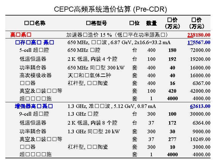
超导高频系统造价比较 (CEPC Pre-CDR) CEPC 1. 3 GHz LCLS-II 1. 3 GHz XFEL 1. 3 GHz ILC-500 1. 3 GHz CEPC 650 MHz 能量 (Ge. V) 5. 12 4 17. 5 500 6. 87 加速梯度 (MV/m) 19. 3 16 23. 6 31. 5 15. 5 品�因数 2 E 10 2. 7 E 10 1 E 10 4 E 10 流强 (m. A) 0. 87 20 % DF 0. 1 CW 2. 3 1 % DF 5. 8 1 % DF 33. 2 CW 超�腔�数 256+44 304 800 16000 384+16 恒温器�数 32+5 38 100 2000 96+4 高�系��价 6. 3 � 6. 8 � 15 � 176 � 17. 6 � 每腔均�造价 210 万 224 万 187 万 110 万 440万 每低温模�造价 1703 万 1789 万 1496 万 880 万 1760 万 每Ge. V造价 1. 26 � 1. 7 � 0. 86 � 0. 35 � 2. 5 � 1 USD = 6. 5 CNY 1 EUR = 8 CNY