CENTIFUGAL PUMP OPERATION Static Suction Head Some Important


 ØGas binding of a centrifugal pump is")


 is used. ØThe main pump discharge")


")
- Slides: 29
CENTIFUGAL PUMP OPERATION
Static Suction Head
Some Important Terminologies 1. Static Suction Lift The distance measured vertically the intake of the pump or the pump is placed above the surface of the liquid in the suction tank. 2. Static Suction Head The distance measured vertically the pump is placed below the surface of the liquid in the suction tank. 3. Static Discharge Head The distance measured vertically the pump is placed below the surface of the liquid in the discharge tank. 4. Total Static Head The vertical distance from the surface of the liquid in the suction tank to the surface of the liquid in the discharge tank. TSH = SSL + SDH TSH = SDH - SSH
5. Velocity Head The energy required to put the liquid in motion. 6. Pressure Head The energy required to impart additional pressure on the liquid to overcome the system pressure. 7. Friction Head The amount of energy required to overcome resistance in the pipes, valves and fittings. 8. Total Dynamic Head The sum of velocity, pressure and friction head. In the suction line it is called DSH In the discharge line it is called DDH 9. Total Head The total energy required to move the fluid from the suction to the discharge point. It is the sum of static and dynamic head.
CENTRIFUGAL PUMP OPERATION Cavitation ØDefinition of cavitation ØEffect of cavitation on pump performance ØIndication that a centrifugal pump may be cavitating ØSteps that can be taken to stop pump cavitation ØHow to avoid pump cavitation
ØDefinition of cavitation The process of the formation and subsequent collapse of vapor bubbles in a pump is called cavitation.
Effect of cavitation on pump performance Three effects of pump cavitation are: ØDegraded pump performance resulting in a fluctuating flow rate and discharge pressure ØExcessive pump vibration ØDestructive to pump internal components (damage to pump impeller, bearings, wearings, and seals)
Pressure profile inside a centrifugal pump.
The shock of the imploding bubbles on the surface of the vane produces a gradual erosion and pitting which damages the impeller. Cavitation damage on an impeller
Erosion of the blades of the mixed flow pump impeller
Indication that a centrifugal pump may be cavitating There are three indications that a centrifugal pump is cavitating. ØNoise ØFluctuating discharge pressure and flow ØFluctuating pump motor current
Steps that can be taken to stop pump cavitation include: ØIncrease the pressure at the suction of the pump. ØReduce the temperature of the liquid being pumped. ØReduce head losses in the pump suction piping. ØReduce the flow rate through the pump. (reduce NPSHR ) ØReduce the speed of the pump impeller. (reduce NPSHR )
How to avoid pump cavitation To avoid cavitation in centrifugal pumps, the pressure of the fluid at all points within the pump must remain above saturation pressure. This can be achieved if: The net positive suction head available must be greater than the net positive suction head required. NPSHA > NPSHR
ØIf the head losses in the pump suction piping can be reduced, the NPSHA will be increased. ØVarious methods for reducing head losses include increasing the pipe diameter, reducing the number of elbows, valves, and fittings in the pipe, and decreasing the length of the pipe.
Calculation of the net positive suction head available NPSH A
Gas Binding (in systems containing dissolved gases) ØGas binding of a centrifugal pump is a condition where the pump casing is filled with gases or vapors to the point where the impeller is no longer able to contact enough fluid to function correctly. ØThe impeller spins in the gas bubble, but is unable to force liquid through the pump. Effect of gas binding ØThis can lead to cooling problems for the pump's packing and bearings.
To avoid gas binding ØCentrifugal pumps are designed so that their pump casings are completely filled with liquid during pump operation. ØPumps in systems containing dissolved gases that are not designed to be self-venting should be periodically vented manually to ensure that gases do not build up in the pump casing.
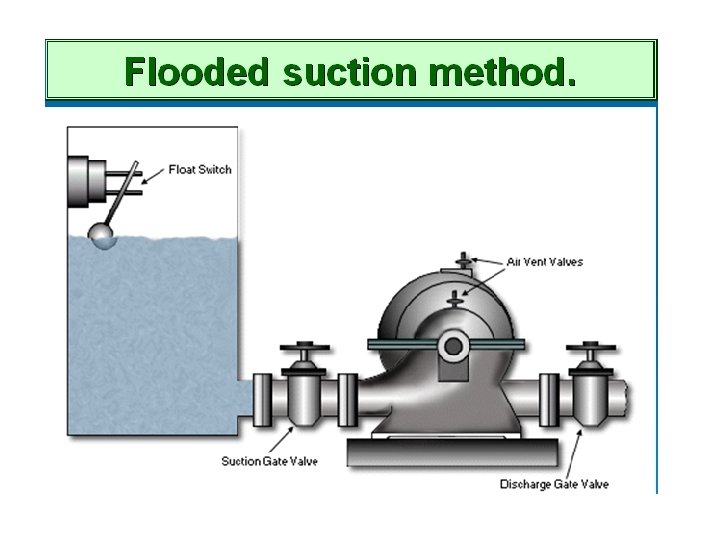
Pump Priming Definition: Filling the pump casing and the suction line with the liquid being pumped. Methods of Priming 1 - If the pump is above the source of supply Øclose the discharge valve and open the suction valve. ØOpen the air vent valves to allow the air in the pump casing to escape. ØWhen water flows from the vents, they can be closed and the pump is then in primed conditions and ready for starting
2 - If the pump is above the source of supply
Fig. a ØThe priming water comes from an external source. ØThe discharge valve is closed and the external supply valve is opened as are the vent valves. ØThe water flows into the pump and into the suction line where it is prevented from escaping by the foot valve. ØThe water fills the suction line and then the pump casing. ØWhen water flows from the vent valves, they and the external supply valve are closed and the pump is ready for starting.
Fig. b ØThe pump is primed by water which is supplied from the pump discharge line. ØThe discharge valve is closed and the priming valve and the air vents are opened. ØWater from the discharge line fills the pump casing and the suction line. ØWhen water flows from the vents, the vent valves and the priming valve are closed and the pump is ready for starting.
3 - Suction Lift Method
ØA separate hand operated priming pump (vacuum pump) is used. ØThe main pump discharge valve is closed and priming pump valve is opened. ØThe priming pump is operated and it exhausts air from the main pump casing and suction line causing water to fill them. ØWhen water flows from the priming pump discharge, then the priming pump is shut and the main pump is ready for starting.
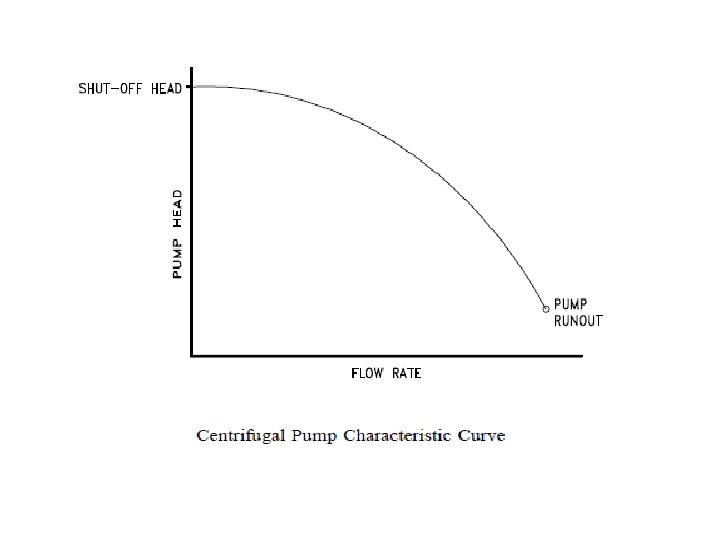
Centrifugal Pump Characteristic Curves ØA vendor manual for a specific pump usually contains a curve of pump flow rate versus pump head called a pump characteristic curve. ØAfter a pump is installed in a system, it is usually tested to ensure that the flow rate and head of the pump are within the required specifications.
ØShutoff head is the maximum head that can be developed by a centrifugal pump operating at a set speed. ØPump runout is the maximum flow that can be developed by a centrifugal pump without damaging the pump. ØCentrifugal pumps must be designed and operated to be protected from the conditions of pump runout or operating at shutoff head.
Pump performance curve Pump operating point Head System curve Static head Flow
Centrifugal Pump Protection ØCentrifugal pumps must be protected from running dead head (shutoff conditions) and runout. ØOne method for protecting the pump from running dead-headed is to provide a recirculation line from the pump discharge line upstream of the discharge valve, back to the pump's supply source. ØCentrifugal pumps must also be protected from runout. Runout can lead to cavitation. ØOne method for ensuring that there is always adequate flow resistance at the pump discharge to prevent excessive flow through the pump is to place an orifice or a throttle valve immediately downstream of the pump discharge.