Unit 46 Advanced Milling Dividing head assessment Targets


 • • Example: 3 sides Measure")


 of serrations / divisions.")
 are used")


- Slides: 35
Unit 46 Advanced Milling Dividing head assessment
Targets: • State the difference between direct and simple indexing. • To calculate 12 different angular spacing’s using simple indexing.
• The dividing head is a device which allows you to very accurately divide a 360° circle into virtually any number of equally spaced divisions.
Index Head Parts
• The plain and universal dividing heads • This type of head is ideal for production work where only basic divisions of a component are required, for example squares and hexagons.
• THE UNIVERSAL DIVIDING HEAD • The chuck of the universal can be swung to any angle between vertical and horizontal and the indexing plate can be used to rotate the chuck.
• The function of a dividing head is to hold and rotate work so that slots, grooves, splines, teeth, flats, etc can be milled around the work-piece circumference at equally spaced distances.
• Activity • Describe the two most commonly used methods of indexing used on a dividing head, explain how they differ and give an example of how each could be used. • Direct • Simple
• Direct indexing • Using pin / lever to locate chuck (generally every 15°) • (360 ÷ 24 = 15°) 24 holes on the plate. • Used for any feature that requires a multiple of 15°, such as ? ? ? ? Direct indexing plate Rapid indexing to common angles, such as 15, 30, 45, 60, 120, degrees.
• Using direct indexing calculate the number of divisions on the direct indexing plate required to produce the following angular divisions: Angle / Divisions Number of holes on direct required indexing plate 1 15° 3 45° 4 60° 6 90° 8 120° 12 180 • Activity • Name 6 shapes that can be machined using direct indexing
• Simple indexing. • To calculate other spacing’s that are not multiples of 15° a method called simple indexing is used, • Work is positioned by means of a crank, index plate, and sector arms. • The crank is attached to the dividing head spindle and one complete turn on the crank will cause the spindle and work to rotate 1 / 40 of a turn, which is equal to 9° (ratio of 40: 1). • 40 X 9 = 360
Index Plate and Sector Arms • Index plate • Circular plate provided with series of equally spaced holes into which index crank pin engages • Sector arms • Fit on front of plate and may be set to any portion of a complete turn 13
• Formulae used for calculating the number of turns and fractions of turns of the crank on a dividing head. • If you are given a number of divisions? • Crank turns = 40 ÷ n • Where n = the required number of divisions at the spindle
Hole plate available – 21 & 27 • Crank turns = 40 ÷ n • Where n = the required number of divisions at the spindle Divisions required Number of turns and partial turns required Equation 4 Hole circle required Rounded No of full Layout to a Remainder up to suit hole on turns fraction plate 40 ÷ 4 = 40 ÷ 5 = 10 8 6 5 4 5 4/6 5/7 14/21 15/21 14 7 40 ÷ 6 = 40 ÷ 7 = Any 21 (DI) 15 21 8 40 ÷ 8 = 5 Any (DI) 9 40 ÷ 9 = 12/27 7/21 12 7 27 40 ÷ 3 = 4 1 4/9 3 4 13 5 6 1/3 R/D Any (DI) 21 (DI) R / D = Remainder and division **Must be rounded up to suit plate**
• Activity • Calculate the number of turns and part turns of the crank for the following: • • Q. 5 flats • • Q. 4 holes • • Q. 11 slots A. 8 full turns A. 10 full turns A. 3, 7/11 or 3, 14/22 or 3, 21/33 Never count the hole or slot in which the index pin is engaged.
• Simple indexing - If you are given an angle • Formulae used for calculating the number of turns and fractions of turns of the crank on a dividing head. • If you are given an angle? • The crank has a ratio of 40: 1, therefore 360 ÷ 40 = 9° (each turn of the crank = 9°) • The formula for angular spacing’s is: angle required 9°
• Calculate the number of turns and part turns of the crank for the following: • Q. 2 holes at 49º to each other • A. 5 4/9 or 5 8/18 • Q. 2 holes at 57º to each other • A. 6 3/9 or 9/27 angle required 9° Layout - Remainder and Angle
Angle required Number of turns and partial turns required No of full Layout to Equation Remainder turns a fraction Rounded No of up to suit holes on plate 39° 39÷ 9 4 3 3/9 9/27 53° 53÷ 9 62÷ 9 5 8 6 9 8 8 6 8/9 24/27 18/27 6 6/9 18/27 6 6 6/9 18/27 13 2 3 7 3/9 7/9 9/27 21/27 6 3 3/9 9/27 62° 87° 78° 60° 120° 25° 57° 87÷ 9 78 60÷ 9 120÷ 9 25 ÷ 9 57 ÷ 9 R/A Hole circle required 9 24 27 27 24 18 18 27 18 9 21 9 27 27 27 R / A = Remainder and Angle
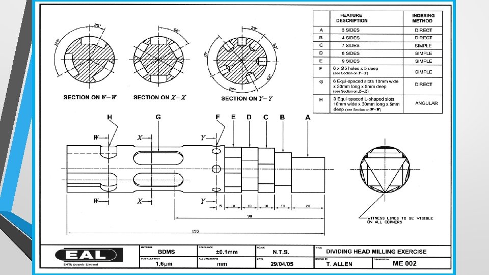
Finding the depth of cut • We can use the chart used to find equally spaced holes, to find the depth of cut for each shaped feature on the dividing head milling exercise.
Finding the depth of cut (3 sides Triangle) • • Example: 3 sides Measure bar diameter (31. 8 mm) 0. 250 x 31. 8 = 7. 95 15. 9 – 7. 95 = 7. 95 Depth of cut is 7. 95 mm Back off 0. 4 mm to leave witness mark. ***
Finding the depth of cut Use the chart to find the depth of cut for the shapes below Number of sides A: 3 SIDES (21 P) B: 4 SIDES (21 P) C: 7 SIDES (21 P) D: 8 SIDES (21 P) E: 9 SIDES (27 P) Divider number Depth of cut *Actual depth of cut 0. 25 7. 95 (Measurement from outside diameter) 7. 5 0. 45 4. 64 (Measurement from outside diameter) 15. 9 – 14. 31 =1. 6 (Measurement from centre line) 0. 46 15. 9 – 14. 63 =1. 27 (Measurement from centre line) 0. 9 0. 469 15. 9 – 14. 91 =0. 99 (Measurement from centre line) 0. 7 0. 146 4. 3 1. 2
Notes: • Holes to be machined clock wise • L slots machined counter clock wise • Looking at the work-piece from the tail stock end
• END
• • Calculating a large number (greater than 40) of serrations / divisions. In this instance use the 40 ÷ n formula and just cancel the result down to a suitable hole circle size; • • Q. 96 serrations • • Q. 135 serrations A. 40 / 135 = 5/27 A. 40 / 96 = 5/12 or 10/24
• Q. Explain why different index plates (containing different hole circles) are used on a dividing head, what do the differing hole circles allow you to do? • A. To give a wider range of divisions as possible
• Q. Describe what a dividing head can be used for, state at least four examples of features that can be produced. • A. Grooves, Slots, Shapes / forms, Gear teeth, Serrations, any feature that is equally spaced or angularly spaced to each other.
• Serrations: • A series or set of teeth or notches. • A single tooth or notch in a serrate edge.
• Q. Name two specialist processes that a dividing head can be used for: • Cam milling • Spiral Milling • Helical Milling
• Q. What types of work holding devices can be used on a dividing head? • 3 jaw chuck • 4 jaw chuck • Face-plate • Centre • Arbour
• Describe the process for mounting a setting a dividing head and tailstock parallel to the machine table?
1. Clean all components, 2. Using suitable lifting equipment and place dividing head on machine table. 3. Place a ground parallel bar in the chuck and secure. Using a dial test indicator with the plunger just touching the bar at the chuck end, wind the cross slide in/out to get a high reading. 4. Wind the horizontal slide down to the other end and repeat. Note the difference and make suitable adjustments until the reading is within tolerance.
• Q. How can the dividing head be set at an angle to the machine table? • A. By undoing the blocking bolts and tilting the dividing head to the correct angle.
• Q. What is meant by the term ‘the hand of the dividing head’? A. The dividing head is either right hand or left hand. This signifies the end of the table that it is to be positioned to carry out spiral or cam milling.
Helical Milling • Q. What safety measures do you think are missing and what other precautions regarding the machine set up do you think need to be taken into account? • Guards • Ensure the work-holding devices don’t foul any part of the machine when moving.