An Introduction To Marine Steam Propulsion Plant Source
![An Introduction To Marine Steam Propulsion Plant [Source: US Navy]](https://slidetodoc.com/presentation_image_h/8b5aa1c5c4196a1b52f14e04421859b8/image-1.jpg "An Introduction To Marine Steam Propulsion Plant [Source: US Navy]")

")


")


")


")

 l MFBP")
 –")


- Slides: 26
An Introduction To Marine Steam Propulsion Plant [Source: US Navy]
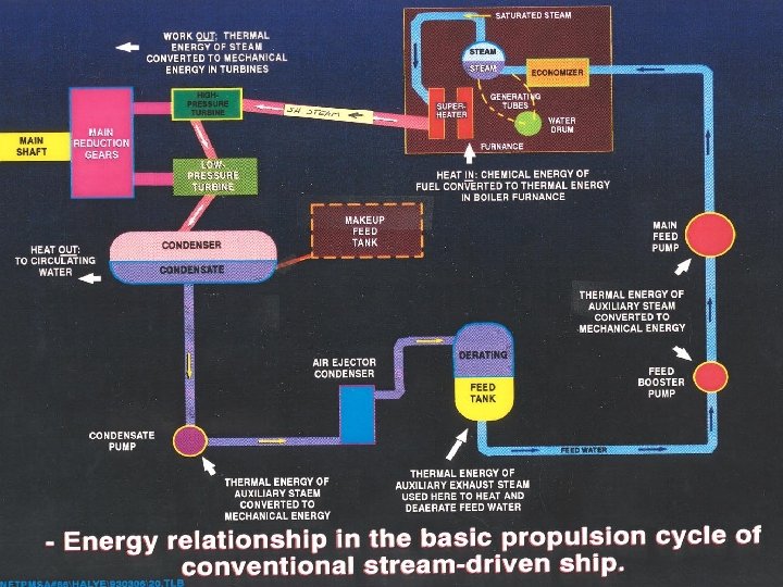
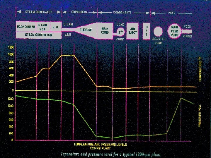
Four Phases of Steam Cycle Generation l Expansion l Condensation l Feed l
GENERATION (Boilers)
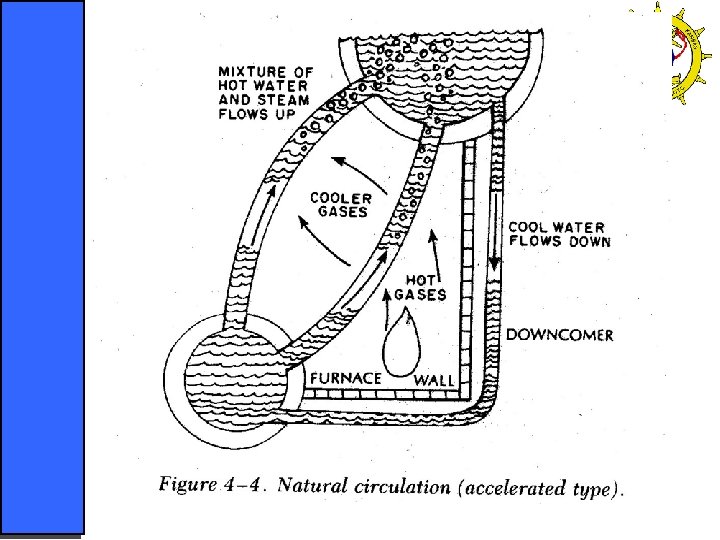
GENERATION l Boiler – fuel is converted to heat – largest and heaviest part of steam plant – heat is transferred via conduction to water in the metal tubes – some of this water becomes steam l Steam drum – as steam is generated it collects in the upper portion of the boiler – steam collecting in the steam drum is called saturated steam
GENERATION l Super heater – saturated steam does not contain enough thermal energy to make the turbines operate efficiently – uses heat from the burner section of the boiler to increase the temperature of the steam – superheated steam is also dryer which helps prevent erosion of the turbine blades and main feed pumps
GENERATION l Economizer – improves efficiency in the steam plant – uses thermal energy that would go up the stack to preheat feedwater before the steam drum – nest of tubes located between the generating tubes of the boiler and the stack
EXPANSION (Turbines)
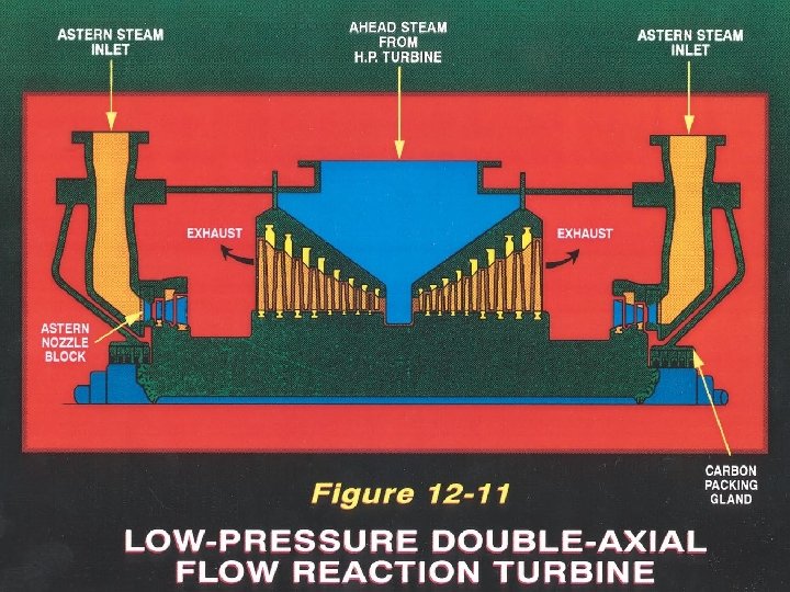
EXPANSION Turbines l High pressure/high temperature steam goes from the superheater outlet to the high pressure turbine of the main engine l – this is where expansion begins – superheated steam expands in the turbine and is converted to mechanical energy to turn the rotor
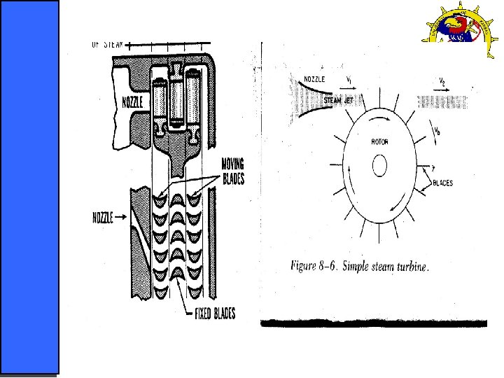
EXPANSION – energy conversion takes place in two steps in each stage of turbine blades – first the steam passes through the nozzles which increase the steam’s velocity – this kinetic energy is then converted into work by the turbine blades – after steam leaves the HP turbine it still has thermal energy – steam undergoes the same process in the LP turbine
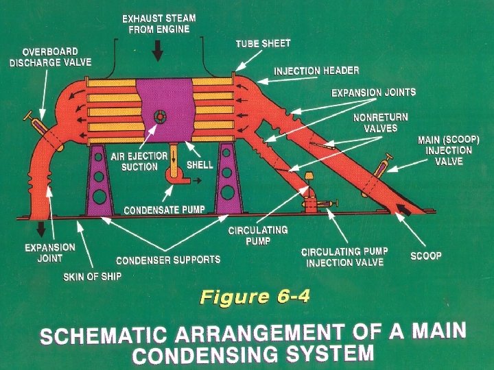
CONDENSATION (Condenser, MCP, AEC)
CONDENSATION l Main Condenser – large sealed container that serves as an indirecttype shell and tube heat exchanger – cool seawater flows through thousands of internal tubes – steam from the exhaust of the LP turbine flows over these tubes and heat is removed from the steam, condensing the steam in to a liquid (Condensate) – The condensing action of the steam creates and maintains a vacuum in the condensers
CONDENSATION l Main condensate pump – one or two stage centrifugal pump, electrically driven – moves condensate from the hotwell through the main air ejector condenser to the deaerating feed tank – pump is drawing a suction on the water in the hotwell – lowest pressure in the system occurs here
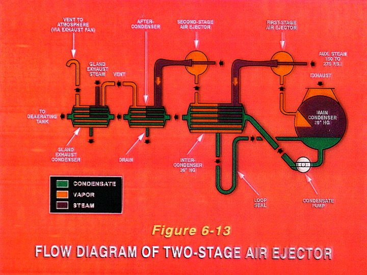
CONDENSATION l Air ejector condenser – shell and tube heat exchanger – two functions § § removes latent heat from the auxiliary steam being discharged by the air ejector transfers heat from the steam to the condensate to preheat it before it enters the deaerating feed tank
FEED (DFT, MFBP, MFP)
FEED PHASE The Deaerating feed tank is the beginning of the feed phase l Direct type heat exchanger - three functions l – feed is heated by auxiliary steam and then falls to the lower section - causing the oxygen held in solution to be removed – heats feed and maintains proper temperature of water – storage tank for heated oxygen free feedwater
FEED PHASE Feedwater goes from deaerating tank to main feed boost pump(MFBP) l MFBP l – one or two stage double suction centrifugal pump – installed below the DFT – discharges into the suction side of the main feed pump (MFP)
FEED PHASE l MFP – Large Multistage Centrifugal pumps (steam or electrically driven) – delivers feedwater in sufficient amounts and develops enough pressure to force the water into the boiler against the pressure of the steam drum
MACHINERY PLANT LAYOUT No two ships are exactly alike l Machinery is arranged in various ways as space and weight permit l Generally speaking l – Propulsion machinery is usually on two levels § § condensers and main reduction gear on lower level propulsion turbines and pinion gears are on upper level
MACHINERY PLANT LAYOUT – Low pressure turbine exhaust is directly above the condenser – Boilers are on the lower and upper levels along the centerline of the ship === END ===