
SPACE PROPULSION BASED ON HIGHBETA MAGNETIC FUSION ROCKET
SPACE PROPULSION BASED ON HIGH-BETA MAGNETIC FUSION ROCKET I. V. Romadanov, S. V. Ryzhkov Bauman Moscow State Technical University E-mail: i. v. romadanov@gmail. com
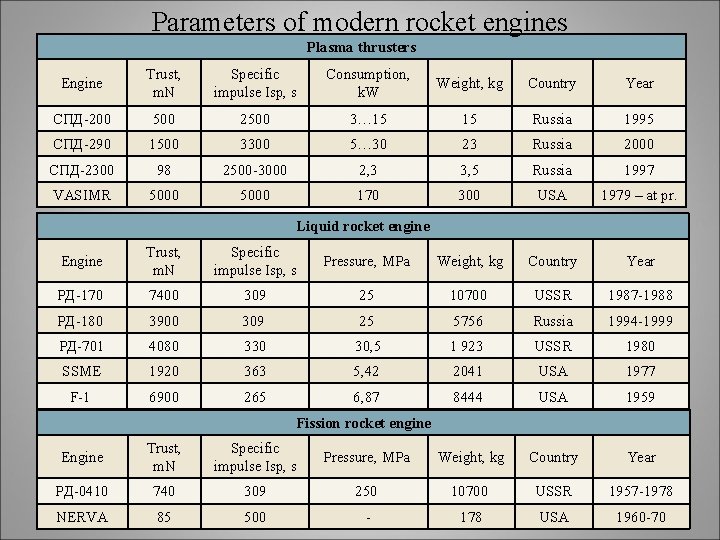
Parameters of modern rocket engines Plasma thrusters Engine Trust, m. N Specific impulse Isp, s Consumption, k. W Weight, kg Country Year СПД-200 500 2500 3… 15 15 Russia 1995 СПД-290 1500 3300 5… 30 23 Russia 2000 СПД-2300 98 2500 -3000 2, 3 3, 5 Russia 1997 VASIMR 5000 170 300 USA 1979 – at pr. Liquid rocket engine Engine Trust, m. N Specific impulse Isp, s Pressure, MPa Weight, kg Country Year РД-170 7400 309 25 10700 USSR 1987 -1988 РД-180 3900 309 25 5756 Russia 1994 -1999 РД-701 4080 330 30, 5 1 923 USSR 1980 SSME 1920 363 5, 42 2041 USA 1977 F-1 6900 265 6, 87 8444 USA 1959 Fission rocket engine Engine Trust, m. N Specific impulse Isp, s Pressure, MPa Weight, kg Country Year РД-0410 740 309 250 10700 USSR 1957 -1978 NERVA 85 500 - 178 USA 1960 -70
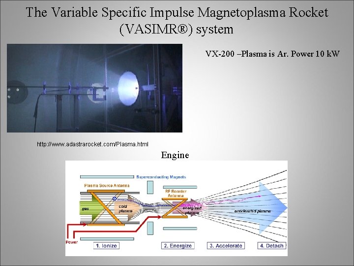
The Variable Specific Impulse Magnetoplasma Rocket (VASIMR®) system VX-200 –Plasma is Ar. Power 10 k. W http: //www. adastrarocket. com/Plasma. html Engine
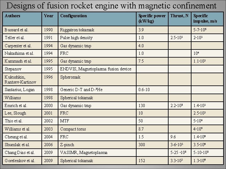
Designs of fusion rocket engine with magnetic confinement Authors Year Configuration Specific power (k. W/kg) Thrust, N Specific impulse, m/s Bussard et al. 1990 Riggatron tokamak 3. 9 Teller et al. 1991 Pulse high density 1. 0 Carpenter et al. 1994 Gas dynamic trap 4. 0 Nakashima et al. 1994 FRC 1. 0 104 Kammash et al. 1995 Gas dynamic trap 7. 5 1. 1∙ 105 Stepanov 1995 ENDVIS, Magnetoplasma fusion device Kukushkin, Rantsev-Kartinov 1996 Spheromak Santarius, Logan 1998 Generic D-T and D-3 He Williams 1998 Spherical tokamak Emrich et al. 2000 Gas dynamic trap 130 Lee, Slough 2001 FRC 10 2. 5∙ 105 Thio et al. 2002 MTF 50 5∙ 104 Williams et al. 2003 Compact torus 8. 7 4∙ 104 Cheung et al. 2004 FRC 1. 5 9. 6 1. 4∙ 106 Shumlak et al. 2006 Z-pinch 300 3 -6∙ 105 3. 5∙ 106 Chang Dias et al. 2009 VASIMR, Magnetoplasma 5 -25 ∙ 103 5 -10∙ 103 Gorelenkov et al. 2009 Spherical tokamak 3. 3∙ 105 1. 3∙ 106 5 -7∙ 103 2. 5∙ 105 2∙ 105 0. 6 -10 152 2. 2∙ 103 1. 4∙ 105
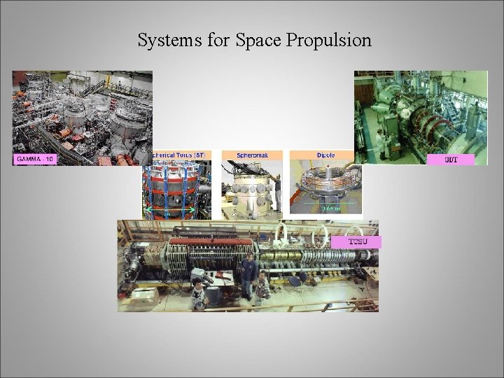
Systems for Space Propulsion
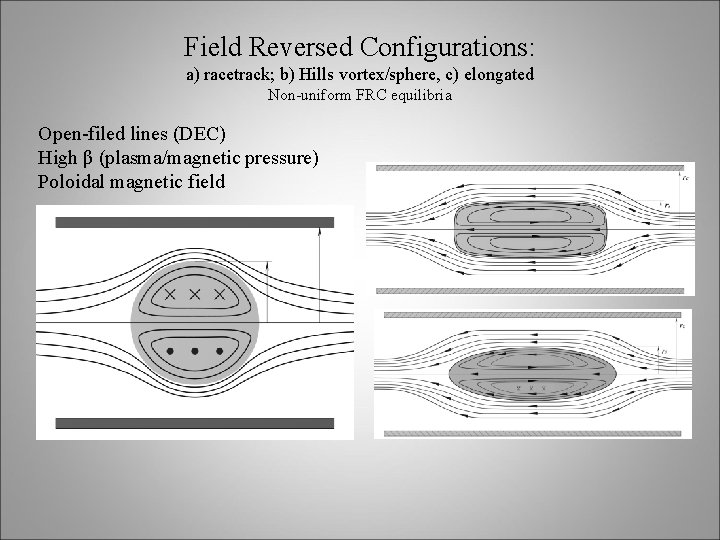
Field Reversed Configurations: a) racetrack; b) Hills vortex/sphere, c) elongated Non-uniform FRC equilibria Open-filed lines (DEC) High β (plasma/magnetic pressure) Poloidal magnetic field
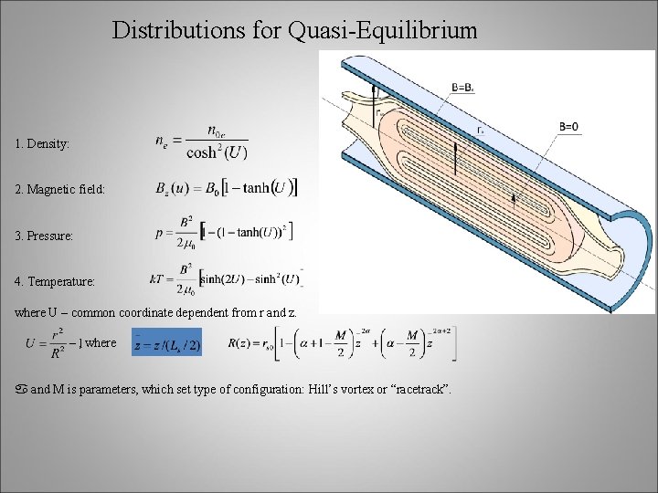
Distributions for Quasi-Equilibrium 1. Density: 2. Magnetic field: 3. Pressure: 4. Temperature: where U – common coordinate dependent from r and z. , where and M is parameters, which set type of configuration: Hill’s vortex or “racetrack”.
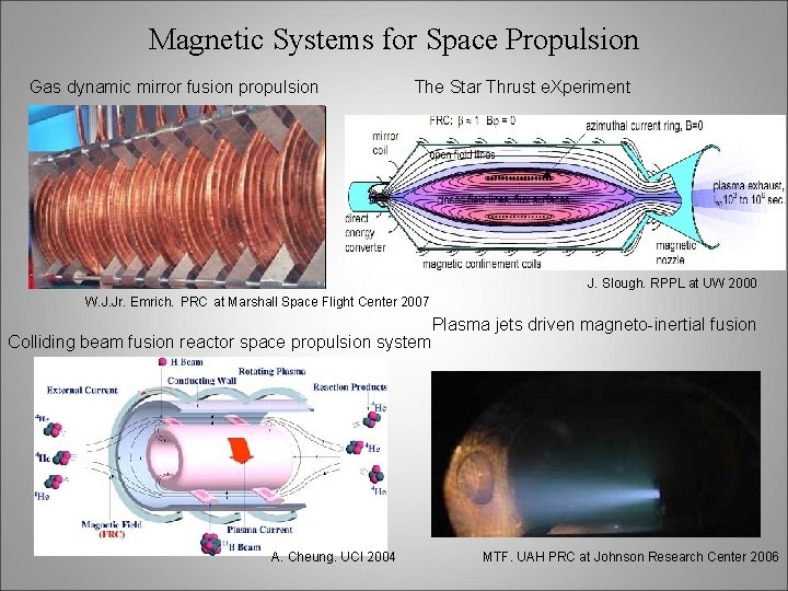
Magnetic Systems for Space Propulsion Gas dynamic mirror fusion propulsion The Star Thrust e. Xperiment J. Slough. RPPL at UW 2000 W. J. Jr. Emrich. PRC at Marshall Space Flight Center 2007 Colliding beam fusion reactor space propulsion system A. Cheung. UCI 2004 Plasma jets driven magneto-inertial fusion MTF. UAH PRC at Johnson Research Center 2006
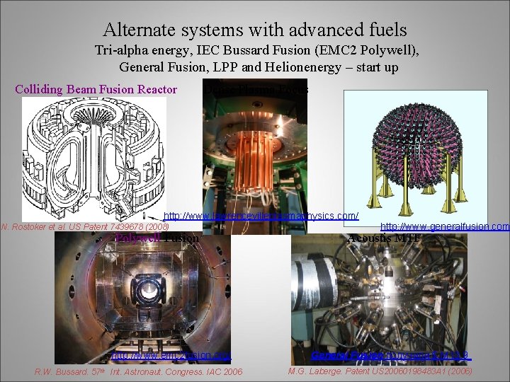
Alternate systems with advanced fuels Tri-alpha energy, IEC Bussard Fusion (EMC 2 Polywell), General Fusion, LPP and Helionenergy – start up Colliding Beam Fusion Reactor Dense Plasma Focus http: //www. lawrencevilleplasmaphysics. com/ N. Rostoker et al. US Patent 7439678 (2008) Polywell Fusion http: //www. emc 2 fusion. org/ R. W. Bussard. 57 th Int. Astronaut. Congress. IAC 2006 http: //www. generalfusion. com Acoustis MTF General Fusion получили $ М 13. 9 M. G. Laberge. Patent US 20060198483 A 1 (2006)
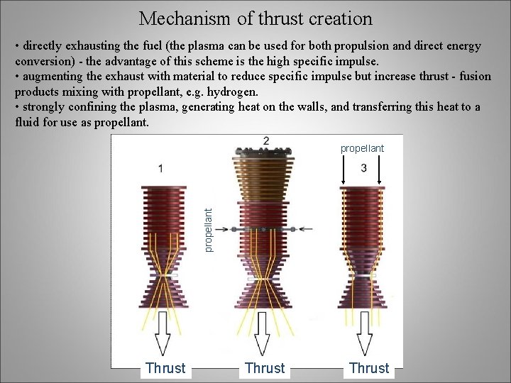
Mechanism of thrust creation • directly exhausting the fuel (the plasma can be used for both propulsion and direct energy conversion) - the advantage of this scheme is the high specific impulse. • augmenting the exhaust with material to reduce specific impulse but increase thrust - fusion products mixing with propellant, e. g. hydrogen. • strongly confining the plasma, generating heat on the walls, and transferring this heat to a fluid for use as propellant Thrust
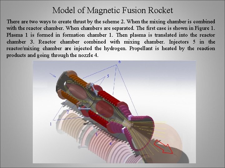
Model of Magnetic Fusion Rocket There are two ways to create thrust by the scheme 2. When the mixing chamber is combined with the reactor chamber. When chambers are separated. The first case is shown in Figure 1. Plasma 1 is formed in formation chamber 1. Then plasma is translated into the reactor chamber 3. Reactor chamber combined with mixing chamber. Injectors 5 in the reactor/mixing chamber are injected the hydrogen. Propellant is heated by the reaction products and going through the nozzle 4.
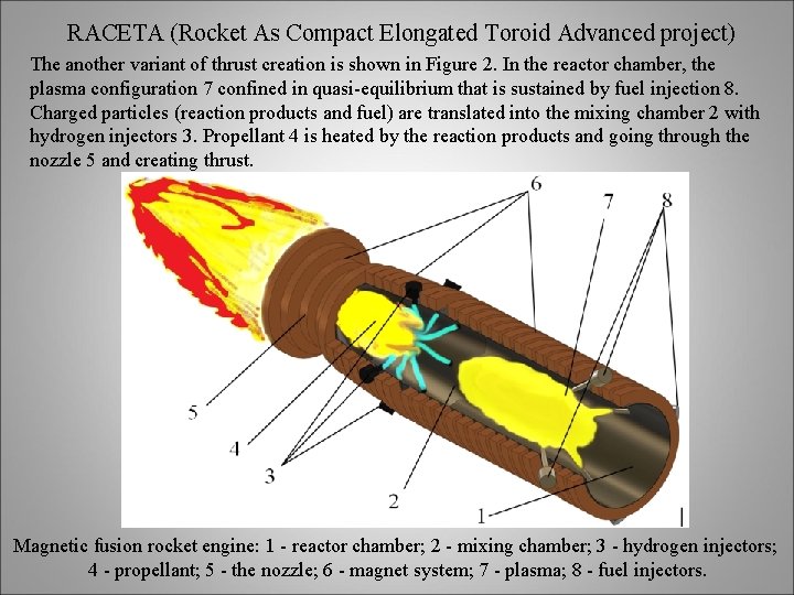
RACETA (Rocket As Compact Elongated Toroid Advanced project) The another variant of thrust creation is shown in Figure 2. In the reactor chamber, the plasma configuration 7 confined in quasi-equilibrium that is sustained by fuel injection 8. Charged particles (reaction products and fuel) are translated into the mixing chamber 2 with hydrogen injectors 3. Propellant 4 is heated by the reaction products and going through the nozzle 5 and creating thrust. Magnetic fusion rocket engine: 1 - reactor chamber; 2 - mixing chamber; 3 - hydrogen injectors; 4 - propellant; 5 - the nozzle; 6 - magnet system; 7 - plasma; 8 - fuel injectors.

Fuels <σv> m 3/s D + T n (14. 07 Me. V) + 4 He (3. 52 Me. V), D + 3 He p (14. 68 Me. V) + 4 He (3. 67 Me. V), D + D n (2. 45 Me. V) + 3 He (0. 82 Me. V), D + D p (3. 02 Me. V) + T (1. 01 Me. V). T, ke. V
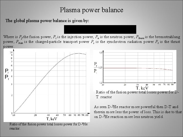
Plasma power balance The global plasma power balance is given by: Where is Pf the fusion power, Pi is the injection power, Pn is the neutron power, Pbrem is the bremsstrahlung power, Ptran is the charged-particle transport power Ps is the synchrotron radiation power Pt is the thrust power. Ratio of the fusion power total losses power for DT reactor As seen D-3 He reactor more powerful then D-T and therein more less the power of loss. This is due to that on D-3 He reaction more less neutron yield. Ratio of the fusion power total losses power for D-3 He reactor.
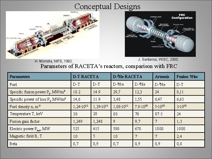
Conceptual Designs J. Santarius, WISC, 2000. H. Momota, NIFS, 1992. Parameters of RACETA’s reactors, comparison with FRC Parameters D-T RACETA D-3 He RACETA Artemis Fusion Wisc Fuel D-T D-3 He D-T Specific fusion power Pf, MW/m 3 18. 2 14. 9 29, 7 12, 3 24 8, 11 Specific power of loss Pl, MW/m 3 14, 6 11. 9 3, 48 1, 55 6, 47 6, 63 Fuel density n, m-3 1, 24∙ 1021 1, 39∙ 1021 1, 08∙ 1021 7. 8∙ 1020 5∙ 1020 3∙ 1020 Temperature T, ke. V 30 20 80 70 87. 5 24 Fusion gain factor 1, 249 1, 248 9 9, 7 7 1, 3 Electric power Pnet, MW 525 415 590 670 1000 Magnetic field B, T 10 5 10 7 7 2, 4 Beta 0, 7 0, 9 0, 8
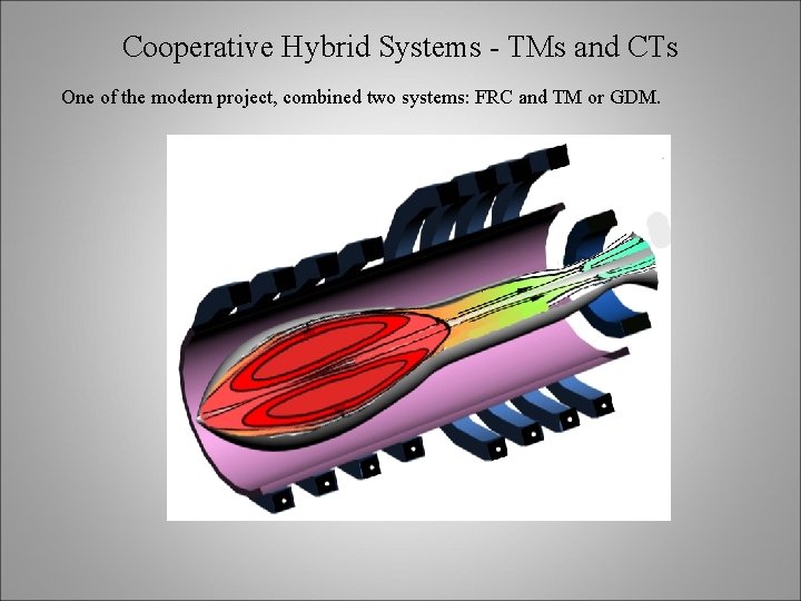
Cooperative Hybrid Systems - TMs and CTs One of the modern project, combined two systems: FRC and TM or GDM.
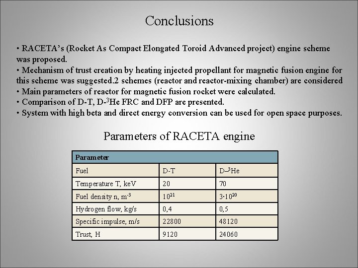
Conclusions • RACETA’s (Rocket As Compact Elongated Toroid Advanced project) engine scheme was proposed. • Mechanism of trust creation by heating injected propellant for magnetic fusion engine for this scheme was suggested. 2 schemes (reactor and reactor-mixing chamber) are considered • Main parameters of reactor for magnetic fusion rocket were calculated. • Comparison of D-T, D-3 He FRC and DFP are presented. • System with high beta and direct energy conversion can be used for open space purposes. Parameters of RACETA engine Parameter Fuel D-T D– 3 He Temperature T, ke. V 20 70 Fuel density n, m-3 1021 3∙ 1020 Hydrogen flow, kg/s 0, 4 0, 5 Specific impulse, m/s 22800 48120 Trust, Н 9120 24060
- Slides: 17