5 7 Flocculation is the process of gentle

 Schematic representation of flocculation process")


 Hydraulic flocculators")


sec = 590")


,")

 The diffusion wall separating flocculation and sedimentation tanks is of")
- Slides: 26
5. 7 Flocculation is the process of gentle and continuous stirring of coagulated water for the purpose of forming flocs through the aggregation of the minute particles present in the water. It is thus the conditioning of water to form flocs that can be readily removed by settling, dissolved air flotation or filtration, Fig (5. 8). The efficiency of the flocculation process is largely determined by the number of collisions between the minute coagulated particles per unit of time.
Fig (5. 8) Schematic representation of flocculation process
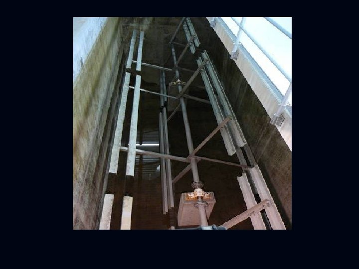
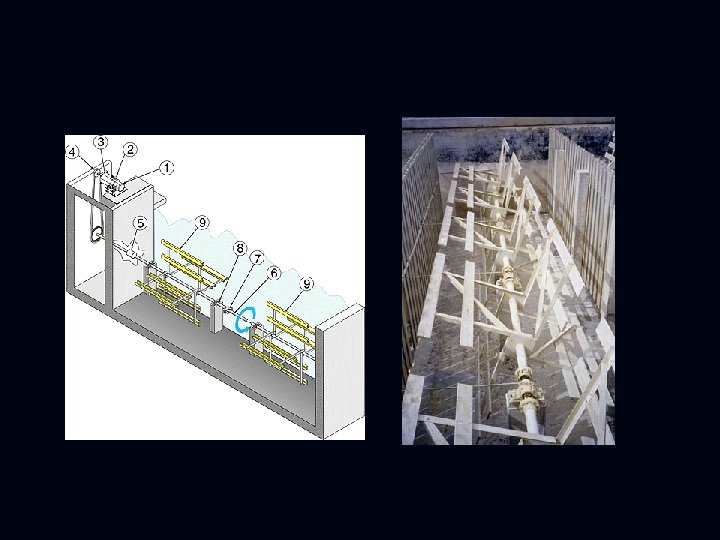
There are mechanical and hydraulic flocculators. In mechanical flocculators the stirring of the water is achieved with devices such as paddles, paddle reels or rakes, as shown in Fig. (5. 9).
There are mechanical and hydraulic flocculators. In mechanical flocculators the stirring of the water is achieved with devices such as paddles, paddle reels or rakes, as shown in fig (5. 9). Fig. (5. 9) Mechanical flocculators
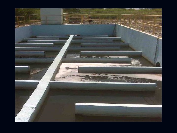
These devices can be fitted to a vertical or horizontal shaft. Vertical shaft flocculators are usually placed in a square tank with several chambers (four or more). With horizontal shaft flocculators having a traverse flow, one should provide at least four rows of shafts, with partitions of baffles, so as to avoid short-circuiting. The hydraulic flocculators utilize horizontal or vertical hydraulic baffled channel as shown in Fig. (5. 10). They are rarely used in large size of water treatment plant, because of their sensitivity to flow changes.
Fig (5. 10) Hydraulic flocculators
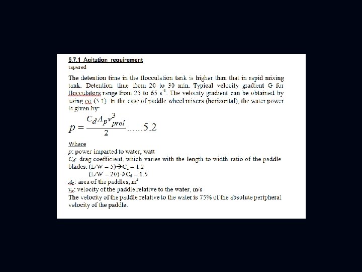
5. 7. 1 Agitation requirement: The detention time in the flocculation tank is higher than that in rapid mixing tank. Detention time from 20 to 30 min. Typical velocity gradient G for flocculators range from 25 to 65 s-1. The velocity gradient can be obtained by using eq. (5. 1). In the case of paddle wheel mixers (horizontal), the water power is given by:
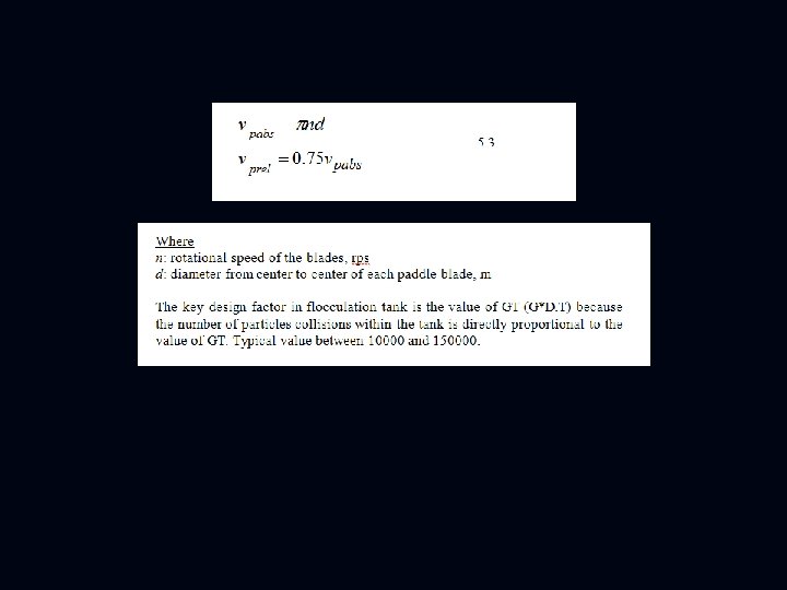
Where p: power imparted to water, watt Cd: drag coefficient, which varies with the length to width ratio of the paddle blades. (L/W = 5)……. . Cd = 1. 2 (L/W = 20)………Cd = 1. 5 A: area of the paddles, m 2 v: velocity of the paddle relative to the water, m/s The velocity of the paddle relative to the water is 75% of the absolute peripheral velocity of the paddle. v = Πnd Where n: rotational speed of the blades, rps d: diameter from center to center of each paddle blade, m The key design factor in flocculation tank is the value of GT (G*D. T) because the number of particles collisions within the tank is directly proportional to the value of GT. Typical value between 10000 and 150000.
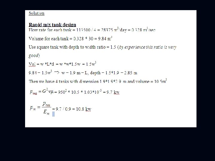
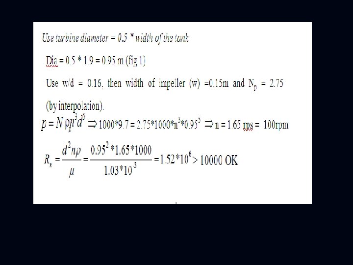
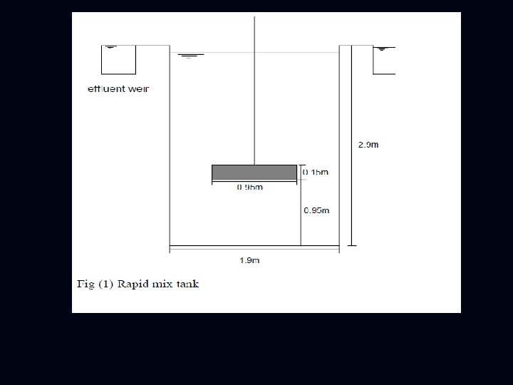
Design of rapid mix and flocculation tanks Flow rate = 113500 m 3/day 1. Rapid mix: Number of tanks = 4 Number of stage = 1 D. T = 30 sec G = 950 s-1 2. Flocculation tank: Number of tanks = 4 Number of stage = 3 D. T = 30 min total, 10 min for each stage G = 60 s-1 (for first stage) G = 30 s-1 (for second stage) G = 10 s-1 (for third stage)
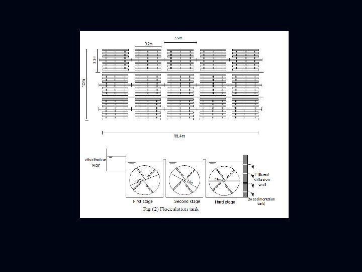
Design flocculation tank Volume = Q*D. T= 0. 328 m 3/s* (30*60)sec = 590 m 3 Volume of each stage of the tank = 590 / 3 = 197 m 3 Width of flocculation tank equal to the width of sedimentation tank, then in this example use w = 18. 4 m, length of each stage = depth Vol = 18. 4*d*d Þ 197 = 18. 4*d 2 Þ d = 3. 27 m use 3. 3 m Vol = 18. 4* 3. 32 =199 m 3 The water flows from one stage to the other through a baffle wall. Total length of three stage = 3. 3*3 = 10 m, fig (2) Volume of each tank = 18. 4 *10*3. 3 m 3
Flocculator power requirement G 1 stage = 60 s-1, volume of each stage = 199 m 3 P 1 stage = 602*199*(1. 03*10 -3) = 0. 737 kw Pm=P/(Em*Ebearings)= 0. 737/(0. 9*0. 7) = 1. 16 kw P 2 stage= 302*199*(1. 03*10 -3) = 0. 184 kw Pm=0. 184 /(0. 9*0. 7) = 0. 29 kw P 3 stage= 152*199*(1. 03*10 -3) = 0. 046 kw Pm=0. 046 /(0. 9*0. 7) = 0. 073 kw Size and number of paddle - Each segment =3. 2 m long - Paddle wheel diameter = 85% of water depth paddle diameter = 0. 85*3. 3 = 2. 9, see fig (2)
Each stage of flocculation tank is provided with 5 segments and each segment has a 12 paddle blades. Each paddle blade is 20 cm wide and 3. 2 m long. The space between two blades is 15 cm, as shown in fig (3). Fig (3) Paddle blades for one segment
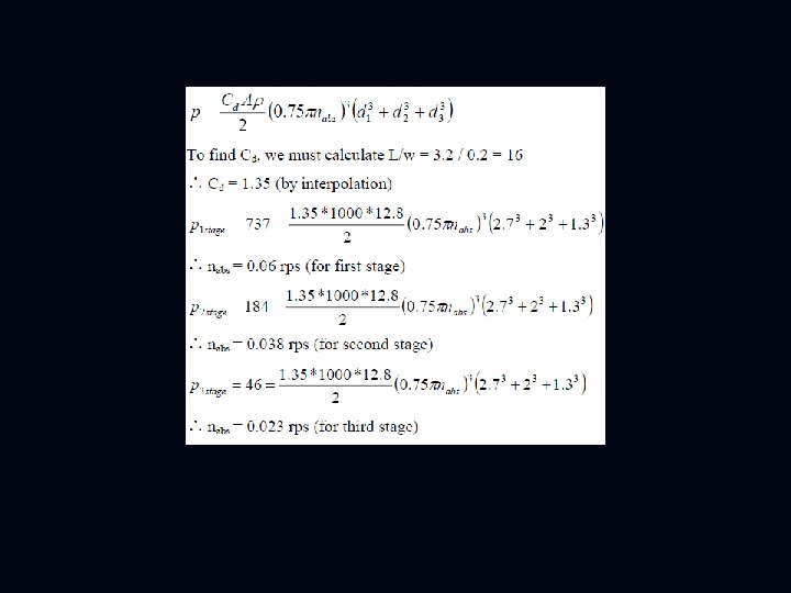
Calculate flocculator speed requirement For paddles are placed at each location (see fig 4), 2. 7 m (2. 9 – 0. 2), 2 m (2. 7 - (0. 1*2 - 0. 15*2)), 1. 3 m center to center. Therefore, the rotational speed is calculated by:
A 1, A 2 and A 3: area of paddles at each location. v 1, v 2 and v 3: velocity of each paddle blade relative to the water. A 1 = A 2 = A 3 = 5 segments per stage * 4 paddle blades at each location per segment * 3. 2 m * 0. 2 m = 12. 8 m 2 v 1 = pnreq d 1= 0. 75 pnabs d 1 v 2 = pnreq d 2= 0. 75 pnabs d 2 v 3 = pnreq d 3= 0. 75 pnabs d 3
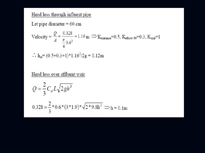
Effluent structure (diffusion wall) The diffusion wall separating flocculation and sedimentation tanks is of concrete, with circular ports. Diffusion wall is used to distribute the flow into the sedimentation tank and consequently to prevent floc breakup. Let velocity through the port = 0. 15 m/sec (to prevent floc breakup) A= Q/v= 0. 328/0. 15=2. 187 m 2 If diameter of port= 12. 5 cm