CE 547 Mixing and Flocculation 1 Mixing Is


 n fluid is thrown towards the")
")
")


 G (s-1) < 10 4000")
 porous ceramic")
 n = number of bubbles")

 l")


 q = flow per unit width of the")


 H = head over the weir crest HD =")


 Type of Raw Water Gt 0 (dimensionless)")

 G decreases")
 CD")


- Slides: 55
CE 547 Mixing and Flocculation
1. Mixing Is a unit operation that distributes the components of two or more materials among the materials producing in the end a single blend of the components. Mixing is accomplished through agitation. Type of mixers: n n n rotational (rotational elements) pneumatic (gas or air bubbles) hydraulic (flowing of water) 2. Flocculation Is a unit operation aimed at enlarging small particles through a very slow agitation. Flocculation is accomplished through the use of large paddles.
Mixing
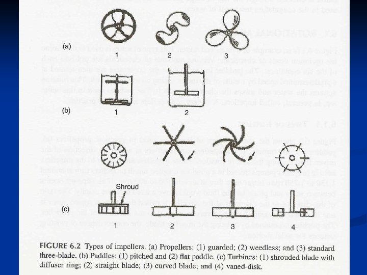
A. Rotational Mixers Impellers are used in rotation mixing. Types of impellers are (Fig 6. 2): a. propellers n n n standard three-blade guarded weedless b. Paddles n flat paddle c. Turbines n n straight blade curved blade vaned-disk shrouded blade
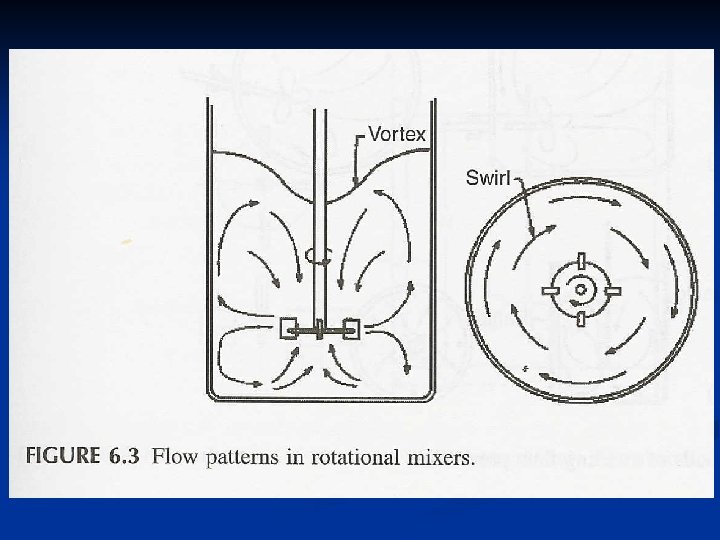
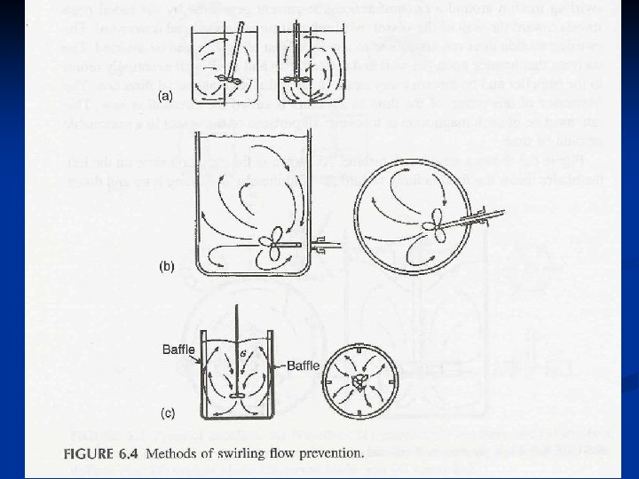
Flow Pattern in Rotational Mixers (Fig 6. 3) n fluid is thrown towards the wall n fluid is deflected up and down n flow returns back to the blades (circulation rate) Prevention of Swirling Flow (Fig 6. 4) n putting the agitator eccentric to the vessel n using a side entrance to the vessel n putting baffles along the vessel wall
Power Dissipation in Rotational Mixers P = function of (N, Da, g, , ) P = power dissipated N = rotational speed Da = diameter of impeller g = acceleration due to gravity = absolute viscosity = mass density
If Re 10 At high Re KL and KT are constants (Power coefficients)
Dt = Diameter of Vessel; W = Width of Paddle; J= Width of baffle
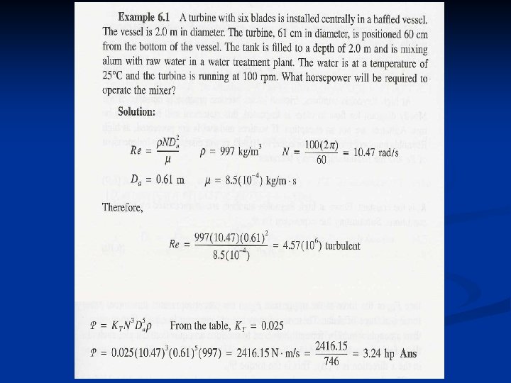
Example 6. 1
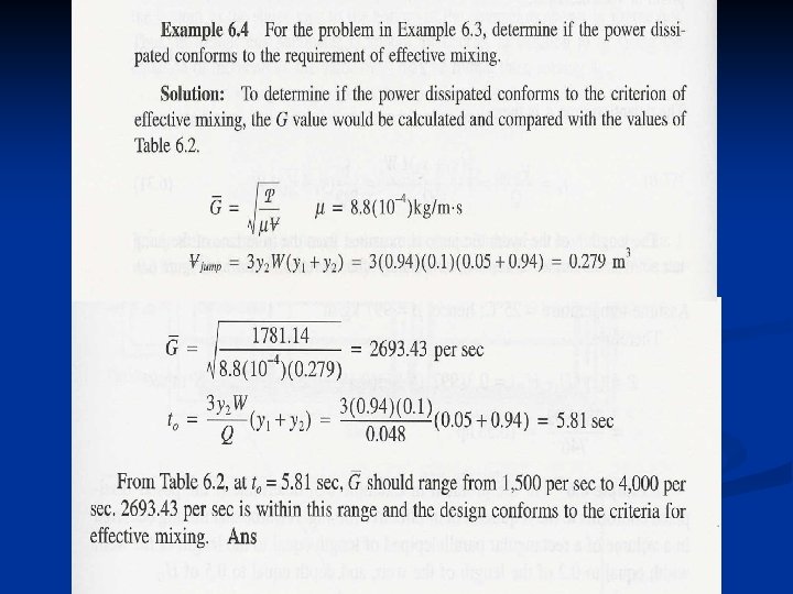
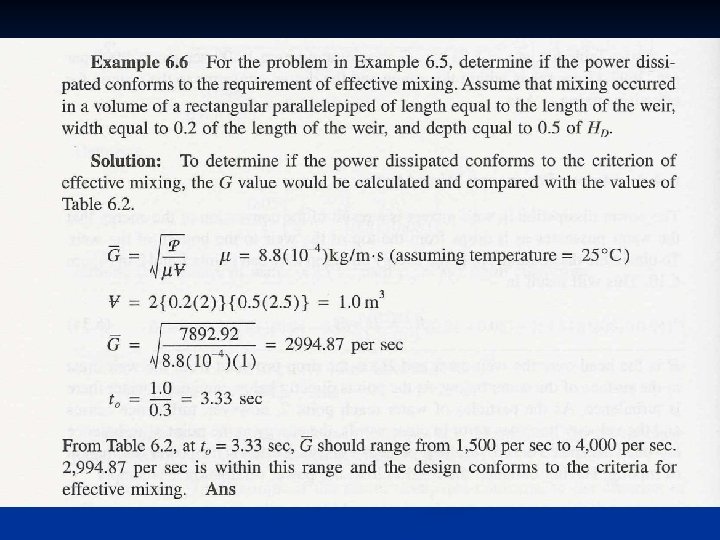
B. Criteria for Effective Mixing G = average velocity gradient in the tank V = volume of tank P = power dissipated = absolute viscosity
G Criteria Values for Effective Mixing t 0 (seconds) G (s-1) < 10 4000 – 1500 10 – 20 1500 – 950 20 – 30 950 – 850 30 – 40 850 – 750 40 – 130 750 – 700 t 0 = detention time of the tank
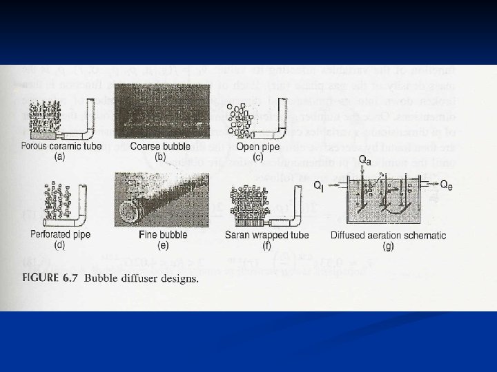
C. Pneumatic Mixers This is accomplished using diffused aerators (Fig 6. 7) porous ceramic tube n coarse bubble n open pipe n perforated pipe n fine bubble n saran wrapped tube n diffused aeration schematic n
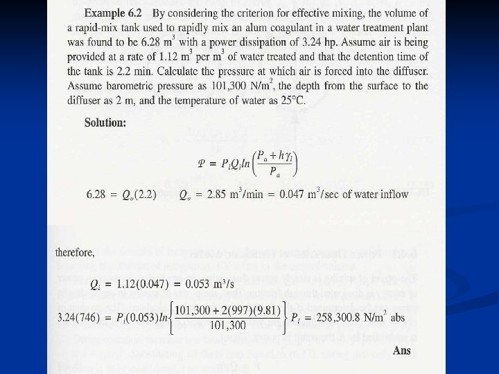
Pneumatic mixing power = function (number of bubbles formed) n = number of bubbles Pi = input pressure to the unit Qi = input flow to the unit Pa = atmospheric pressure b = average rise velocity of bubbles h = depth of submergence of air diffuser Vb 0 = average volume of bubble at surface
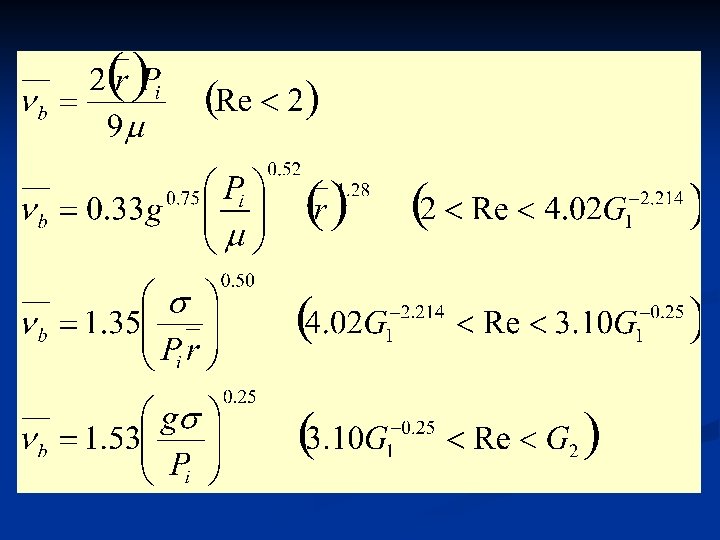
b is described in terms of three dimensionless quantities, G 1, G 2 and Re G 1 = Peebles number G 2 = Garber number = surface tension of fluid r = average radius of bubbles
Power Dissipation in Pneumatic Mixers Qi = input flow to the unit (air) l = specific weight of water
Example 6. 2
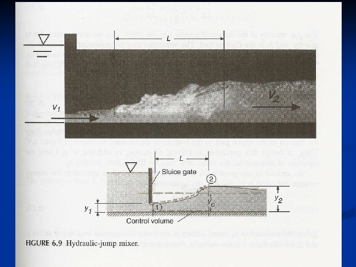
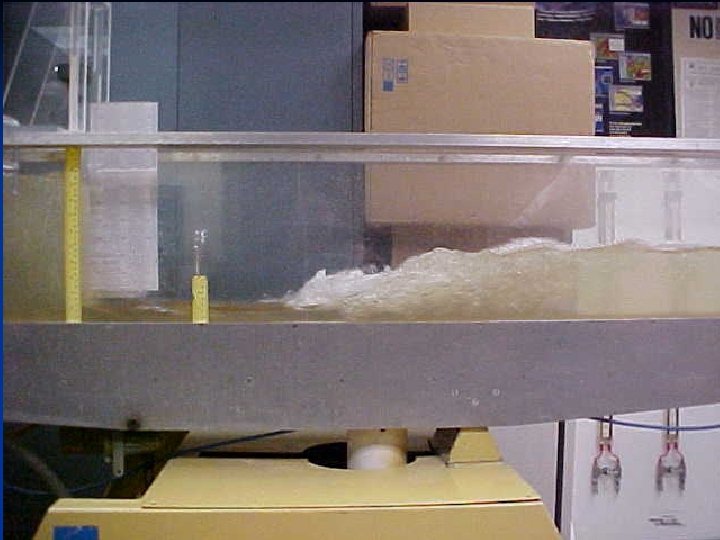
D. Hydraulic Mixers This is accomplished by the use of energy of a flowing fluid to create the power dissipation required for mixing. Types of hydraulic mixers include: hydraulic jump mixer n weir mixer n
Power Dissipation in Hydraulic Mixers hf = fluid friction loss Q = flow rate = specific weight
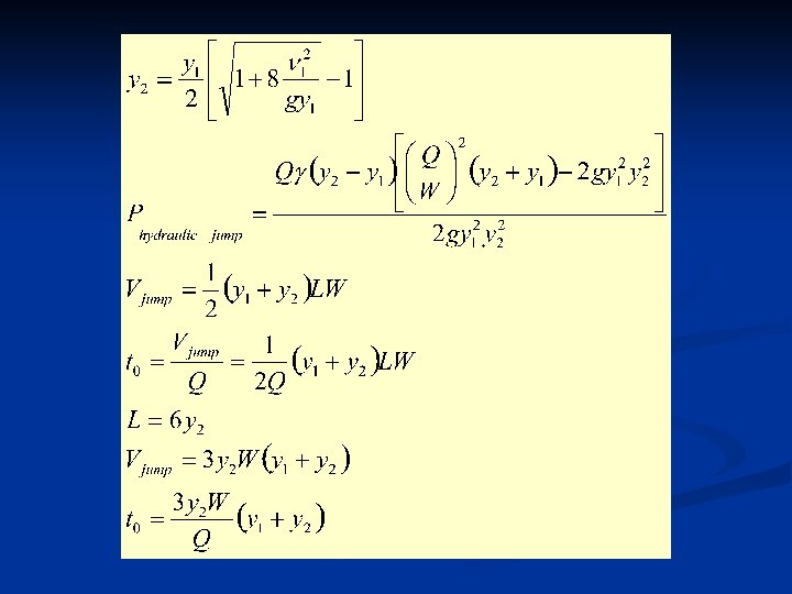
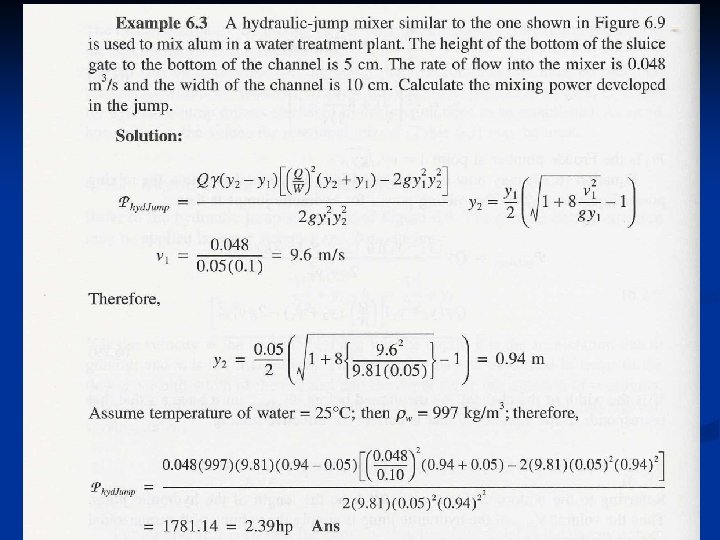
For hydraulic jump (Fig 6. 9) q = flow per unit width of the channel
Using the momentum equation Solving for y 1 and y 2, then
Examples 6. 3 and 6. 4
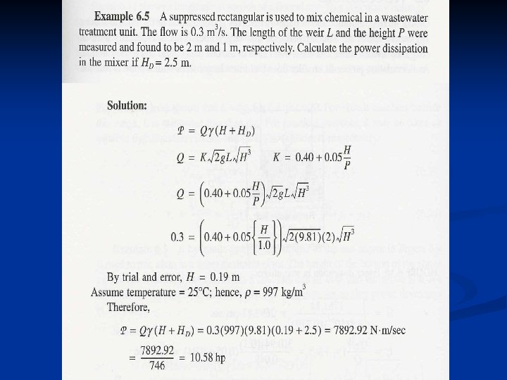
For weirs (Fig 6. 10) H = head over the weir crest HD = drop provided from weir crest to surface of the water below Then
Examples 6. 5 and 6. 6
Flocculators
n n n Agitation in flocculation involves gentle motion of the fluid to induce agglomeration of smaller particles into larger flocs Small flocs build into larger sizes until a point reached where the size can not go on increasing (critical size) Critical size depends on: n n n Detention time (larger detention time produce larger critical sizes) Velocity gradient (larger velocity gradients produce smaller critical sizes) Critical values for effective flocculation are expressed in terms of: n n Gt 0 and G
Critical Values for Effective Flocculation G (s-1) Type of Raw Water Gt 0 (dimensionless) Low turbidity and colored 20 – 70 50, 000 – 250, 000 High turbidity 70 - 150 80, 000 – 190, 000
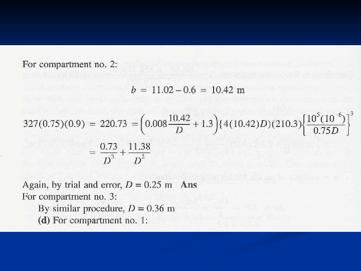
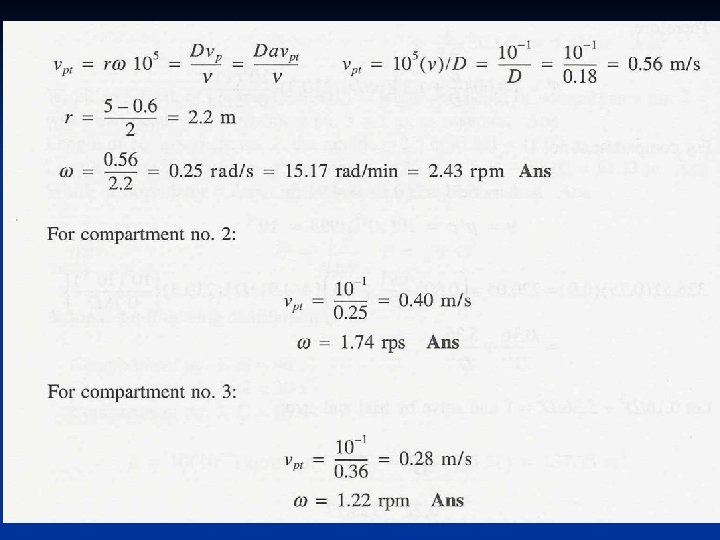
n n n n Compartments vary in size (from smaller to larger) G decreases instead As flow gets larger, rotation of paddle must be made slower to avoid breaking up the flocs The number of blades decrease also as water moves from compartment to another If FD is drag by water on the blade and FD is also the push of the blade upon the water Due to that, water will move at a velocity p equal to the velocity of blade Since paddle is rotating, ( p) is a tangential velocity
rp = radial distance to rotational axis = angular rotation (radians / time) CD = drag coefficient Ap = projected area of blade in the direction of its motion = mass density of water
Total power = sum of powers in each blade Apt = sum of projected area of blade pt = blade tip velocity
n n n Due to location of blades, there will be several p’s To use one velocity, pt, is used multiplied by a factor (a), [ a = 0. 75 ] G and Gt 0 are to be checked to see if the flocculator performs at conditions of effective flocculation Paddle tip velocity should be less than 1. 0 m/sec CD is a function (Re) p = blade velocity n = kinematic viscosity n
For one single blade at Re = 105 CD = for multiple blades must be determined
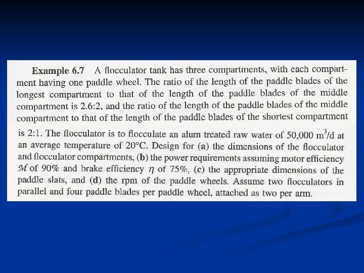
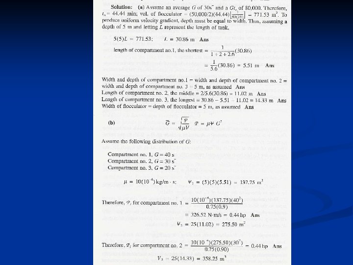
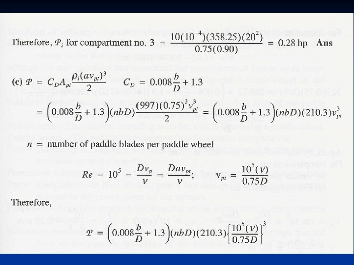
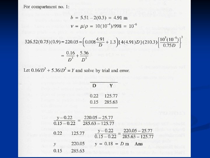
Example 6. 7