CE 370 Coagulation and Flocculation Definitions l Coagulation


![Ferrous Sulfate l Requires alkalinity in the form of hydroxide to react rapidly [Ca(OH)2]](https://slidetodoc.com/presentation_image_h2/e0e675f31528eb09a62e556cc101f9dd/image-12.jpg "Ferrous Sulfate l Requires alkalinity in the form of hydroxide to react rapidly [Ca(OH)2]")
3 is dense")

![Lime Slaked lime or hydrated lime are used l Slaked lime [Ca(OH)2] l l](https://slidetodoc.com/presentation_image_h2/e0e675f31528eb09a62e556cc101f9dd/image-15.jpg "Lime Slaked lime or hydrated lime are used l Slaked lime [Ca(OH)2] l l")

 l Cationic (+vely charged) l Polyampholites (both +vely and –vely")


 l Used with ferric")


 G (sec -1) 20 1000 30 900 40 790 50")


(W)(1. 25 W) =")
 OR l Pneumatic")


(45 min)(60 sec/min) = 72,")


- Slides: 50
CE 370 Coagulation and Flocculation
Definitions l Coagulation Is l The addition and rapid mixing of coagulants l The destabilization of colloidal and fine particles l The initial aggregation of destabilized particles l Flocculation Is l The gentle agitation to aggregate destabilized particles to form rapid-settling floc
Theory of Coagulation l Colloidal Characteristics l Destabilization
Colloidal Characteristics l Nonsettleable Solids l Have l particle size between 0. 1 and 100 micron Colloids l Have particle size between 0. 001 to 1. 0 micron Most of nonsettleable solids are colloidal particulates l Colloids do not settle by the force of gravity l Are stable in suspensions l
Colloidal Characteristics Have large surface area per unit volume l Adsorb substances from surrounding water l Have electrostatic charge l Can be hydrophilic (organic colloids) or hydrophobic (inorganic colloids) l Attract ions of opposite charge to its surface (fixed layer and diffused layer) l
Figure 8. 3
Destabilization l When coagulant is added, destabilization occurs due to the following interactions: l Agitation results in collision of particles l Aggregation of particles by interparticle bridging l Enmeshment of particles in the precipitate that is formed Coagulant salts dissociate when added to water and produce positively charged hydroxo-metallic ion complexes (Meq(OH)pz+) l These complexes tend to polymerize l
Destabilization l For aluminum salts l For iron salts l When complexes adsorb to the surface of the colloid, the zeta potential is reduced and particle is destabilized Destabilized particles aggregate by attraction due to van der Waals forces or chemical interactions between reactive groups available on the surface of the colloid l
Destabilization Coagulants are used in excess of the amounts needed to form the hydroxometallic complexes l The excess complexes will form insoluble hydroxides [Al(OH)3 or Fe(OH)3] l While precipitating, the hydroxides enmesh the negative colloids (sweep coagulation) l For dilute suspensions, the use of large amount of coagulant may re-stabilize the colloids l
Coagulants l Mainly aluminum and iron salts l Aluminum sulfate l Ferrous sulfate l Ferric chloride l Lime [Ca(OH)2] l Aluminum salts are cheaper but iron salts are more effective over wider p. H range
Aluminum Sulfate l To produce the hydroxide floc, enough alkalinity should present in the water l If alkalinity is not enough, then it should be added. Usually hydrated lime is used for that purpose (optimum p. H is 4. 5 – 8)
Ferrous Sulfate l Requires alkalinity in the form of hydroxide to react rapidly [Ca(OH)2] l The p. H should be raised to about 9. 5 and excess lime is stabilized More expensive than alum l
Ferric Sulfate l It reacts with alkalinity presents in water l Fe(OH)3 is dense and settle fast If alkalinity is not enough, hydrated lime is used Optimum p. H is between 4 and 12 l l
Ferric Chloride l It reacts with natural alkalinity l If alkalinity is insufficient, lime is added l Optimum p. H is 4 - 12
Lime Slaked lime or hydrated lime are used l Slaked lime [Ca(OH)2] l l Produced l by reacting quicklime [Ca. O] with water Hydrated lime [Ca(OH)2]
Coagulant Aids l Are used to produce quick-forming, dense and rapid-settling flocs l Polyelectrolytes l p. H adjustment l Alkalinity addition l turbidity addition
Polyelectrolytes Anionic (-vely charged) l Cationic (+vely charged) l Polyampholites (both +vely and –vely charged groups) l Natural such as starch l Synthetic (more common in coagulation) l They aid in coagulation by: l l Chemical bridging l Interaction between reactive groups on the polyelectrolyte and the floc
p. H Adjustment Is used if p. H of water to be treated is not within the optimum p. H of the coagulant l p. H is increased using lime l p. H is reduced using sulfuric acid l
Alkalinity Addition Is used when natural alkalinity is not enough to produce good floc l Hydrated or slaked lime is used l Soda ash (Na 2 CO 3) is also used (expensive) l
Turbidity Addition Is used to provide sufficient particulate concentration to achieve rapid coagulation through sufficient interparticle collision l Is done by recycling chemically precipitated sludge l Clays are also used for that purpose l
Jar Test l Is used to determine: l Proper coagulant aid l Proper coagulant dose l Procedure l Time for floc formation l Floc size l Settling characteristics l Turbidity and color removal (%) l p. H of supernatant
Chemical Feeders l Solution-feed Type l Not desirable (more labor) l Used with ferric chloride l Dry-feed Type
Rapid Mixing and Flocculation l Rapid mixing is used to: Disperse chemicals uniformly throughout the mixing basin l Allow adequate contact between the coagulant and particles l Microflocs are produced l l Flocculation is used to: l Agglomerate microflocs to larger ones
Devices l Agitation in rapid mixing and flocculation is performed by: l Mechanical agitators (most common) l Pneumatic agitators l Baffled basins
Design l The degree of mixing is based on the power provided, which is measured by the velocity gradient: G = velocity gradient, sec-1 l W = power imparted per unit volume of basin, N-m/s-m 3 l P = power imparted, N-m/s l V = basin volume, m 3 l = absolute viscosity of water ( =0. 00131 N-s/m 2) l
Design l The velocity gradient is: = specific weight of water l h. L = head loss due to friction and turbulence l T = detention time l
Velocity Gradient l The rate of particle collision G l Shear force G l Total number of particle collisions GT
Rapid Mixing l Mixing devices l Retention time l Types of impellers
Mixing Devices
Detention Time T (seconds) G (sec -1) 20 1000 30 900 40 790 50 or more 700
Rotary Mixing l Rotary mixing devices can be l Turbines l Paddle impellers l propellers Basins are either circular or square in plan l Depth of basin is 1 to 1. 25 of the basin diameter or width l Baffled tanks are recommended since they minimize vortexing and rotational flow l
Turbine Impellers
Flow Regime
Paddle Impeller
Flow Regime of Propeller
Example – Rapid Mixing A square rapid-mixing basin, with a depth of water equal to 1. 25 times the width, is to be designed for a flow of 7570 m 3/d. The velocity gradient is to be 790 mps/m, the detention time is 40 seconds, the operating temperature is 10 C, and the turbine shaft speed is 100 rpm. Determine: • The basin dimensions • The power required
Solution Find the volume of the basin, The dimensions are (W)(W)(1. 25 W) = 3. 50 m 3 W = 1. 41 m The depth of the basin, H = (1. 25)(1. 41 m) = 1. 76 m Use W = 1. 41 m; H = 1. 76 Using the velocity gradient equation
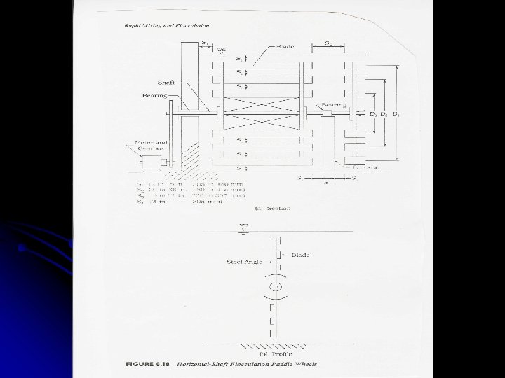
Flocculation l Agitation is provided by: l Mechanical agitation (most common) OR l Pneumatic agitation l Mechanical agitation is provided using: Paddle wheels (most common) l Turbines l Propellers l l Baffles are not used since G and GT are limited
l Complete flocculation depends on: l Ease l Aggregation rate l Number of particle collisions l OR in other words, it depends on: l Floc characteristics l. G l GT Fragile flocs require low G values (<5/sec) l High-strength flocs require high G values ( 10/sec) l
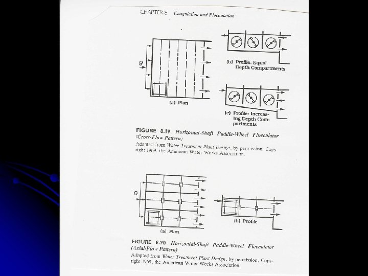
Flocculation Basins Designed to provide tapered flocculation [decreasing G values (high 50 to low 20 to lower 10/sec)] l Horizontal and vertical shafts are used to mount the paddle wheel l Flocculation basins are composed of minimum 3 compartments to: l l Minimize short circuiting l Facilitate tapered flocculation
Flocculation Basins l For cross-flow, tapered flocculation can be provided by: l Varying the paddle size l Varying the number of paddles l Varying the diameter of the paddle wheels l Varying the rotational speed of the various shafts l For axial-flow, tapered flocculation can be provided by: l Varying the paddle size l Varying the number of paddles
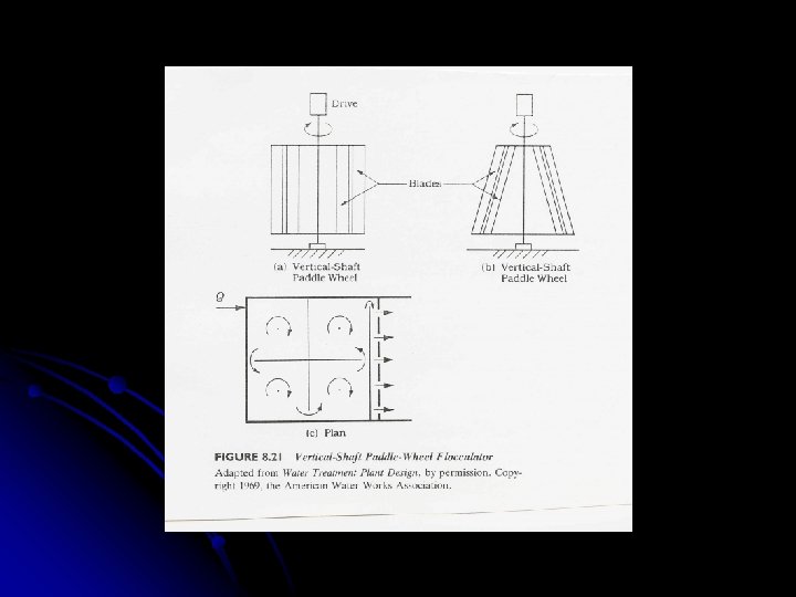
Vertical Shafts l Compartments are arranged to: l Minimize short circuiting l Facilitate tapered flocculation
Example on Flocculation A cross-flow, horizontal shaft, paddle wheel flocculation basin is to be designed for a flow of 25, 000 m 3/d, a mean velocity gradient of 26. 7/sec (at 10 C), and a detention time of 45 minutes. The GT value should be from 50, 000 to 100, 000. Tapered flocculation is to be provided, and the three compartments of equal depth in series are to be used. The G values determined from laboratory tests for the three compartments are G 1 = 50/sec, G 2 = 20/sec, and G 3 = 10/sec. These give an average G value of 26. 7/sec. The compartments are to be separated by slotted, redwood baffle fences, and the floor of the basin is level. The basin should be 1. 5 m in width to adjoin the settling tank. Determine: 1. 2. 3. The GT value The basin dimensions The power to be imparted to the water in each compartment
Example on Flocculation Solution The GT value = (26. 7/sec)(45 min)(60 sec/min) = 72, 100 Since GT value is between 50, 000 and 100, 000, the detention time is satisfactory. Basin volume, V = (flow) (detention time) = (25, 000 m 3/d)(45 min)(hr/60 min) = 781 m 3 Profile area = (volume / width) = (781 m 3 / 15 m) = 52. 1 m 2 Assume compartments are square in profile, and x is the compartment width and depth. Thus, (3 x)(x) = 52. 1 x 2 = 17. 37 x = 4. 17 m 3 x = 3(4. 17) = 12. 51 m Then, width = depth = 4. 17 m length = 12. 51 m volume = (4. 17)(12. 51)(15. 0) = 783 m 3 The Power, P = G 2 V (at 10 C, = 0. 00131 N-s/m 2) P (for first compartment) = (0. 00131 N-s/m 2)(502/s 2)(783 m 3/3) = 855 N-m/s = 855 J/s = 855 W P (for second compartment) = (0. 00131)(202)(783/3) = 137 W P (for third compartment) = (0. 00131)(102)(783/3) = 34. 2 W
Coagulation & Flocculation in Wastewater Treatment The same aluminum and iron salts are used in wastewater l Wastewater requires higher dosages ( 300 mg/l) and coagulates faster than surface water l Beside coagulation, lime and iron salts remove phosphorous l Coagulant aids include polyelectrolytes, addition of turbidity and lime addition l
Coagulation & Flocculation in Wastewater Treatment Rapid-mixing basins have detention time of 1 to 2 minutes (due to high SS and large coagulant dosage) l Velocity gradients in rapid-mixing basins are about 300/sec, which are lower than those for water (due to nature of organic solid) l GT and T are lower than those used with water l
Coagulation & Flocculation in Wastewater Treatment l For alum and iron salts l. T is typically 15 to 30 min l G is typically 20 to 75/sec l GT is typically 10, 000 to 100, 000 l For lime l. T is typically 1 to 2 min in rapid-mixing basins l T is typically 5 to 10 min in flocculation basins l G is typically 100/sec