Wide Dynamic range readout preamplifier for Silicon Strip


- Slides: 16
Wide Dynamic range readout preamplifier for Silicon Strip Sensor Atsushi Taketani, RIKEN M. Kurokawa, A. Takuma Rikkyo University T. Motobayashi, H. Murakami , K. Yoneda RIKEN Y. Togano GSI 1. Requirements from experiments 2. Methods 3. Dual Gain preamp 4. Variable Gain amp 5. Summary
Requirements for SAMURAI Si detector system Coulomb breakup exp. proton SAMURAI heavy particle (z < 50) ich to r on up t o pr ticle r pa 0 Sn 0 0 1 5 Definition of dynamic rang 9 cm upper limit / lower limit (= 4 of detection I. Effective area ~ 9 cm × II. Position resolution ~ 1 mm III. Dynamic range of the electronics ~ 10^4 • coincident measurement from proton (z = 1) to heavy ions (z ~ 50) 2500 • Pileup of beam events
Some Idea • Different gain preamp on different place – Low gain for high Z particle – High gain for proton – Beam size may be bigger than HI-Proton separation • Need high dynamic range preamp.
Response function Linear Detector out ~ Z^2 3000 2500 Linear case: Large ADC bit Square ROOT : Good Log : Small separation at higher Z 2000 1500 Linear 1000 500 0 0 10 Z 20 30 40 50 Squqare ROOT 60 60 Log 4, 000 3, 500 50 3, 000 40 2, 500 2, 000 30 1, 500 ROOT Squqare 20 Log 1, 000 10 0, 500 0, 000 0 0 20 40 Z 60
Specification of a Si detector single-sided strip detector developed GLAST satellite is employed Ref. ) T. Ohsugi et al. , “Design and properties of the GLAST flight silicon micro-strip sensors”, Nucl. Instr. and Methods, A 541 (2005) 29 - 39. signals from 3 strips are grouped together on the PCB readout pitch = 228 mm × 3 = 68 6 in. --> 325 mm number of signal channels / dete = 384 / 3 = 128 ch. total number of signal channels = 128 × 5 = 640 ch.
Architecture I: dual channel system Input charge is divided in proportion to the capacitance ratio between coupling capacitances Ch and Cl (Ch > Cl). Ref. ) N. Uematsu and S. Nishimura, “Development of silicon strip detector with wide-dynamic-range readout system from 20 ke. V to 4 Ge. V”, RIKEN Accel. Prog. Rep. 41, (2008) 151. Qh = Qin × Ch / (Ch + Cl) CSA Qin Ch Cl CSA Ql = Qin × Cl / (Ch + Cl) high-gain channel low-gain channel Log Vout Extended as much as th capacitance ratio similar response with single channel system H L Log Qin 4 p. C 40 p. C Ch = 10 × Cl
Output pulse shapes from the CSAs CSA Ch Cl CSA H This part is implemented in first proto L ßChip and its test board TSMC 0. 5 mm process chip size ~ 1. 6 mm × 1. 2 mm
Result I: Dynamic range for a single channel CSA pulser 104 103 CSA SA-HG SA-LG ADC-H ADC-L 102 101 5. 2 fc 100 10 -3 ADC-H ADC-L 5. 6 pc 10 -2 10 -1 100 101 102 Definition of lower limit = 4 s. 4. 4 f. C corresponds to 100 ke. V. Dynamic range ~ 10^3
Result II: Dynamic range for dual channel CSAs pulser 560 p. F SA-HG ADC-H-H SA-LG ADC-H-L CSA 56 p. F Dynamic range ~ 10^4 CSA SA-LG 10 times wider than that is obtained for the single channel usage ADC-L-L 104 103 102 101 100 56 pc 5. 8 fc 10 -3 10 -2 Definition of lower limit = 4 s 10 -1 100 101 102 ADC-H-H ADC-H-L ADC-L-L
Variable gain Concept D 1: Normal Si Diode Vdrop = 0. 6 V D 2: Schottky Diode Vdrop = 0. 3 V Using different forward voltage drop.
Simulation and measurement
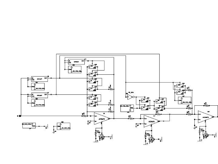
IC chip concept • Difficult to make a Diode on CMOS chip. • Use multiple comparators and CMOS switches • Approximately square ROOT response. CMP. Vth 1 SW 1 R 0 Input Output AMP.
DC response
Large signal case Small Signal case
Summary • Proton break up experiments need wide dynamic range Si Tracker for delta-E measurement • We compared Linear, Log, and square root method. • We have been developing dual gain preamplifier. • We are developing ROOT amp. – Submit Dec 2011. – Will receive 2012 March.