Time domain reflectometry Echo measurement similar to a
- Slides: 24
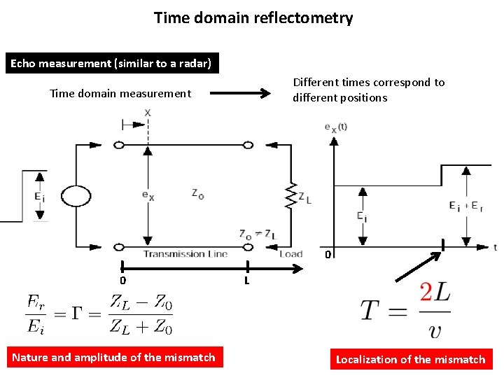
Time domain reflectometry Echo measurement (similar to a radar) Different times correspond to different positions Time domain measurement I 0 Nature and amplitude of the mismatch I 0 I L Localization of the mismatch
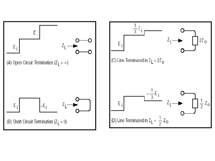
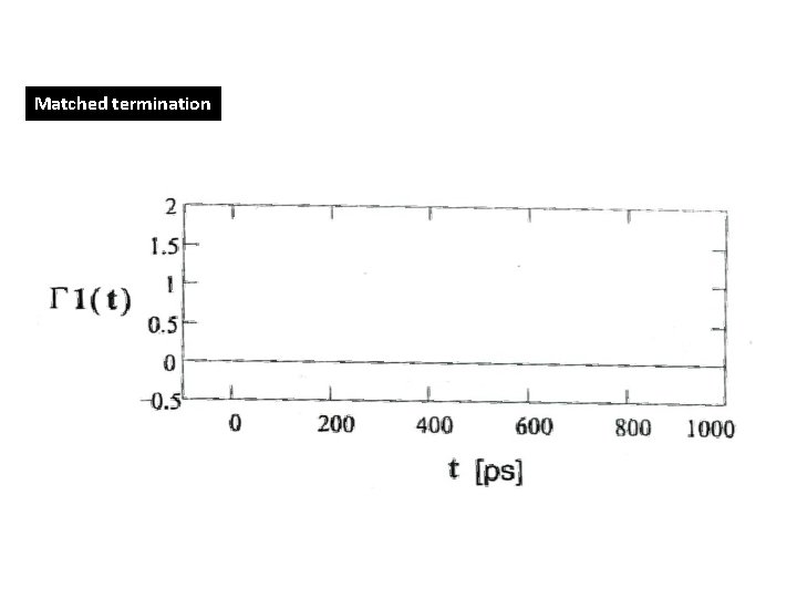
Matched termination
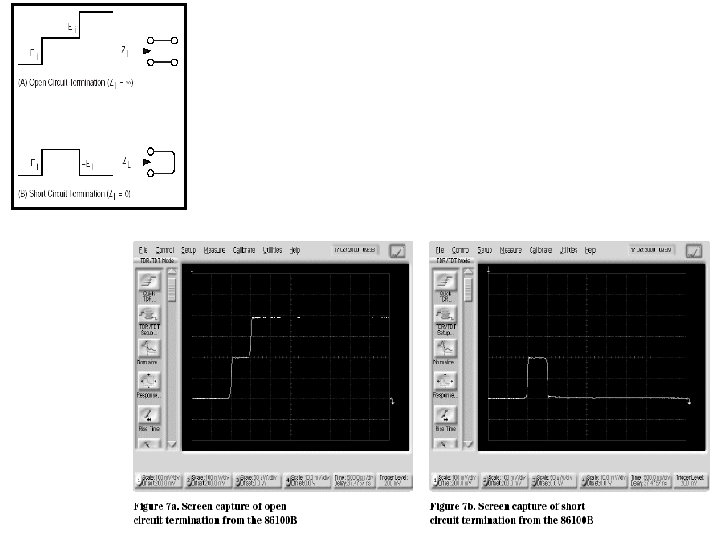
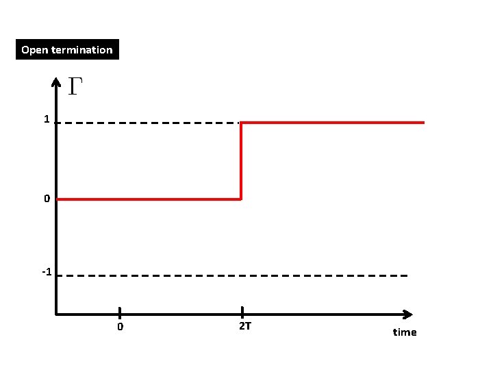
Open termination 1 0 -1 I 0 I 2 T time
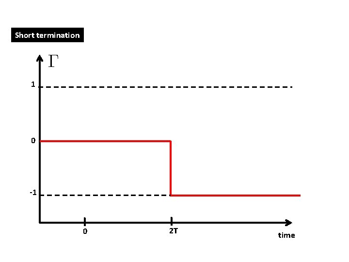
Short termination 1 0 -1 I 0 I 2 T time
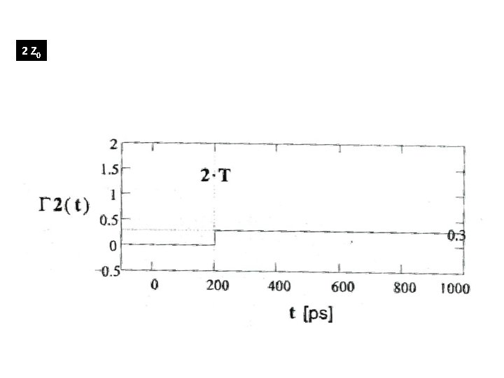
2 Z 0
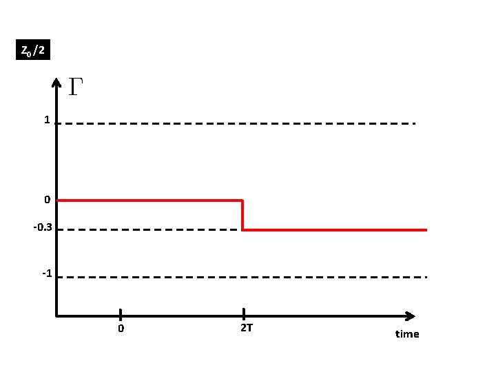
Z 0 /2 1 0 -0. 3 -1 I 0 I 2 T time
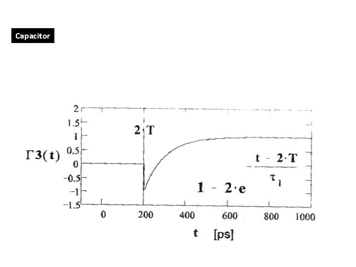
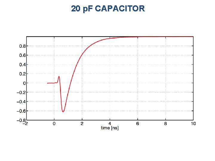
Capacitor
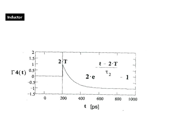
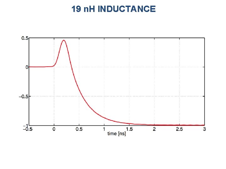
Inductor
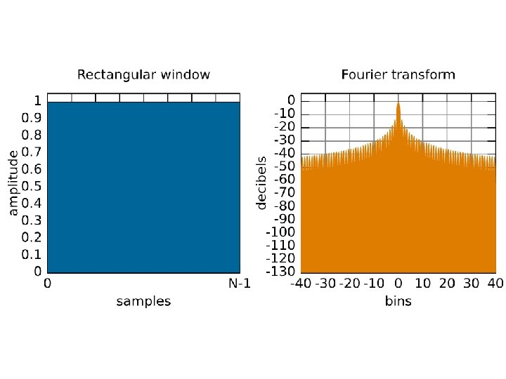
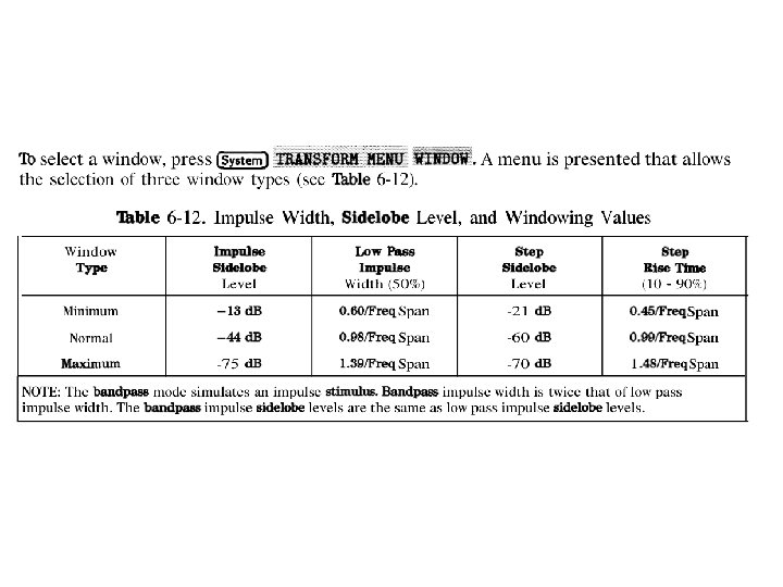
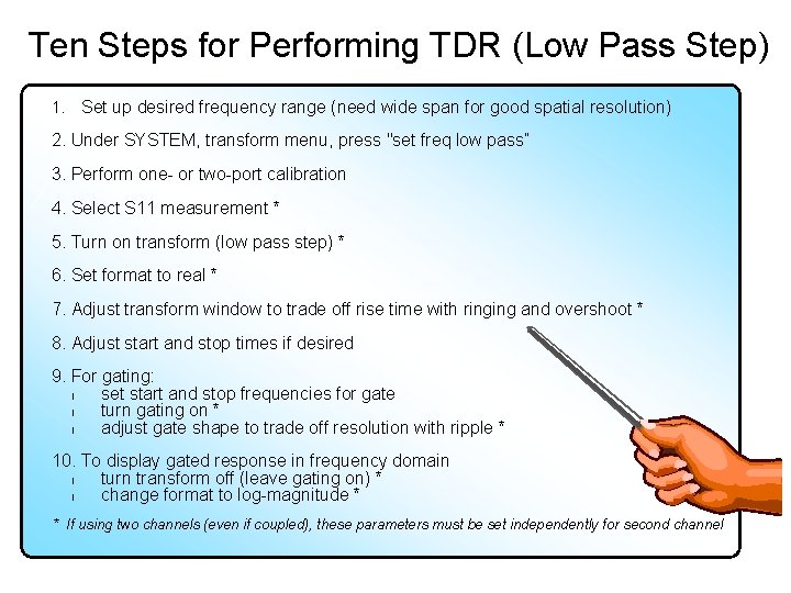
Ten Steps for Performing TDR (Low Pass Step) 1. Set up desired frequency range (need wide span for good spatial resolution) 2. Under SYSTEM, transform menu, press "set freq low pass“ 3. Perform one- or two-port calibration 4. Select S 11 measurement * 5. Turn on transform (low pass step) * 6. Set format to real * 7. Adjust transform window to trade off rise time with ringing and overshoot * 8. Adjust start and stop times if desired 9. For gating: l set start and stop frequencies for gate l turn gating on * l adjust gate shape to trade off resolution with ripple * 10. To display gated response in frequency domain l turn transform off (leave gating on) * l change format to log-magnitude * * If using two channels (even if coupled), these parameters must be set independently for second channel
20 p. F CAPACITOR
19 n. H INDUCTANCE
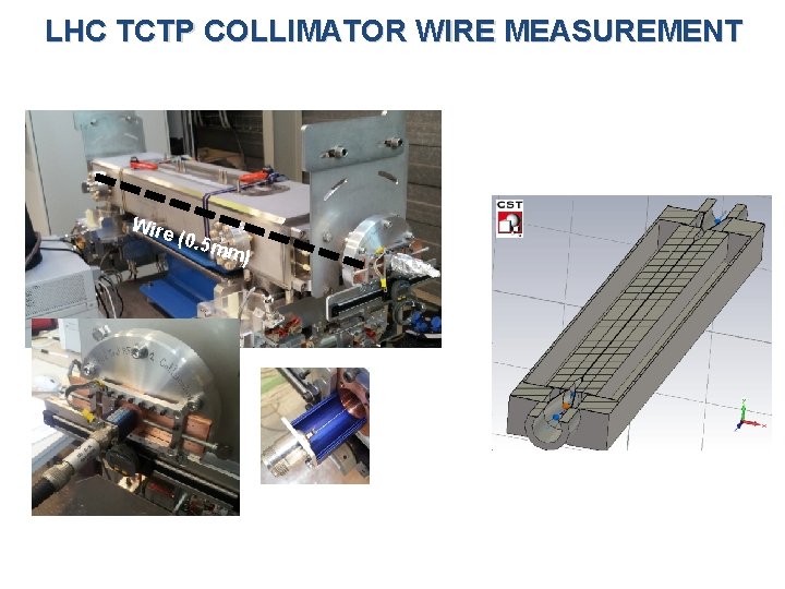
LHC TCTP COLLIMATOR WIRE MEASUREMENT Wire (0. 5 m m)
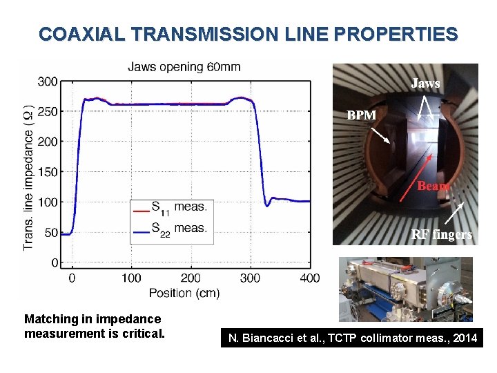
COAXIAL TRANSMISSION LINE PROPERTIES Matching in impedance measurement is critical. N. Biancacci et al. , TCTP collimator meas. , 2014