Thermal Mapping Drone MDR Team 17 Jamyang Tenzin
- Slides: 34
Thermal Mapping Drone MDR Team 17 Jamyang Tenzin Stefan Totino Dylan Fallon Jason Fellow Advisor: Joseph Bardin ECE Department 1
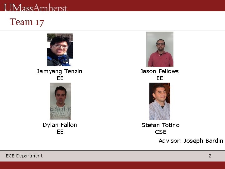
Team 17 Jamyang Tenzin EE Jason Fellows EE Dylan Fallon EE Stefan Totino CSE Advisor: Joseph Bardin ECE Department 2
What’s the purpose? RC Drone survey house Collects thermal data Allows user to analyze data Provides insight into buildings energy waste ECE Department 3
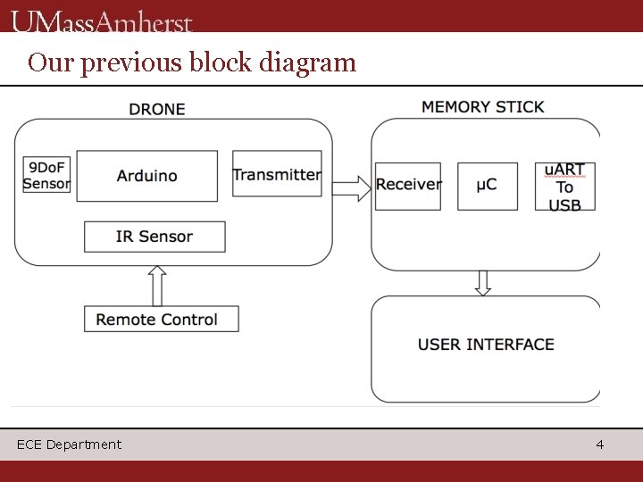
Our previous block diagram ECE Department 4
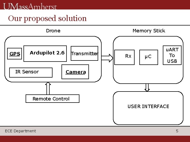
Our proposed solution Drone GPS Memory Stick Ardupilot 2. 6 IR Sensor Transmitter Rx μC u. ART To USB Camera Remote Control USER INTERFACE ECE Department 5
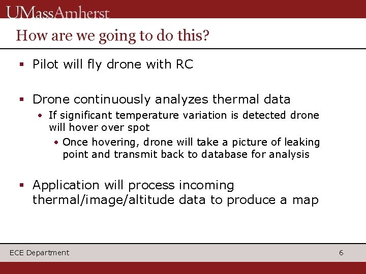
How are we going to do this? Pilot will fly drone with RC Drone continuously analyzes thermal data • If significant temperature variation is detected drone will hover spot • Once hovering, drone will take a picture of leaking point and transmit back to database for analysis Application will process incoming thermal/image/altitude data to produce a map ECE Department 6
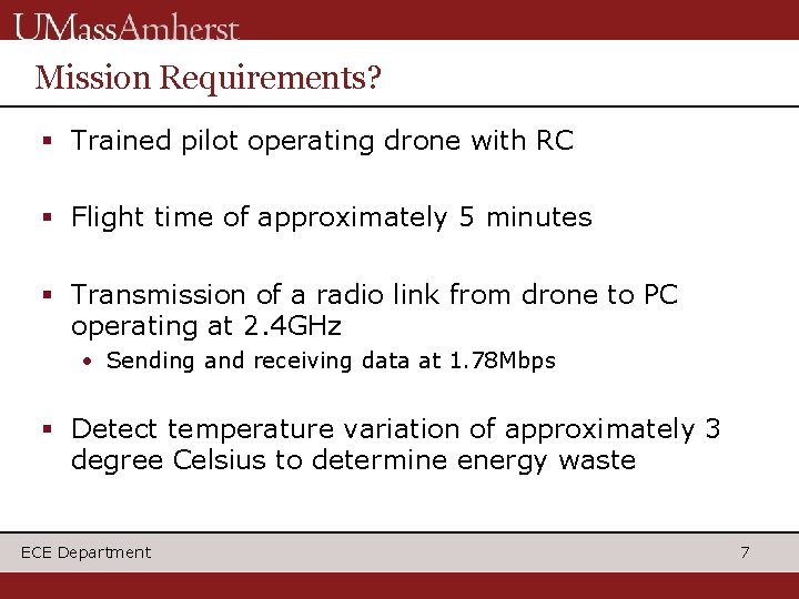
Mission Requirements? Trained pilot operating drone with RC Flight time of approximately 5 minutes Transmission of a radio link from drone to PC operating at 2. 4 GHz • Sending and receiving data at 1. 78 Mbps Detect temperature variation of approximately 3 degree Celsius to determine energy waste ECE Department 7
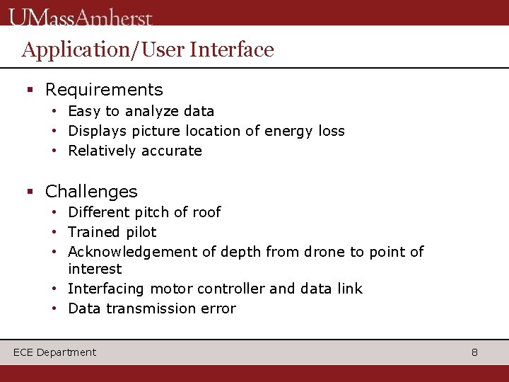
Application/User Interface Requirements • Easy to analyze data • Displays picture location of energy loss • Relatively accurate Challenges • Different pitch of roof • Trained pilot • Acknowledgement of depth from drone to point of interest • Interfacing motor controller and data link • Data transmission error ECE Department 8
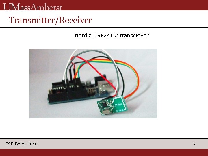
Transmitter/Receiver Nordic NRF 24 L 01 transciever ECE Department 9
About transceiver 11. 3 m. A for transmission, 12. 3 m. A for receiving 1. 78 Mbps data transmission Operates at 3. 3 V max Power is 60 m. W Transmitter and receiver are controlled on both ends by arduino Operates at 2. 4 GHz on ISM band ECE Department 10
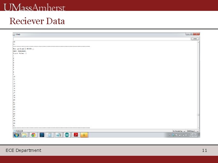
Reciever Data ECE Department 11
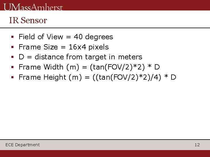
IR Sensor Field of View = 40 degrees Frame Size = 16 x 4 pixels D = distance from target in meters Frame Width (m) = (tan(FOV/2)*2) * D Frame Height (m) = ((tan(FOV/2)*2)/4) * D ECE Department 12
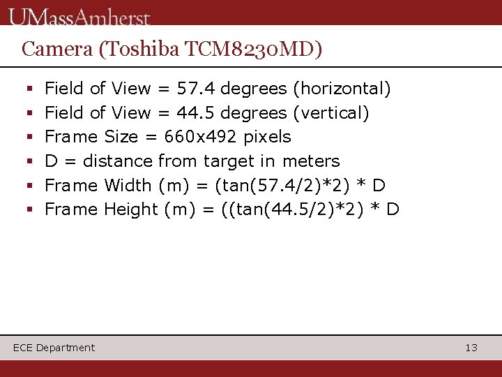
Camera (Toshiba TCM 8230 MD) Field of View = 57. 4 degrees (horizontal) Field of View = 44. 5 degrees (vertical) Frame Size = 660 x 492 pixels D = distance from target in meters Frame Width (m) = (tan(57. 4/2)*2) * D Frame Height (m) = ((tan(44. 5/2)*2) * D ECE Department 13
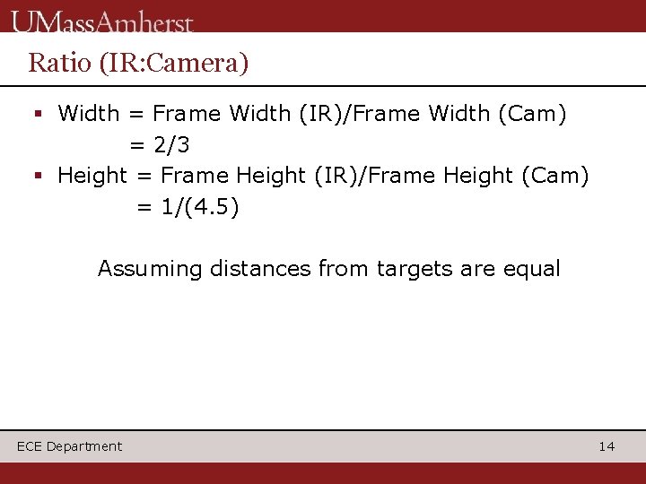
Ratio (IR: Camera) Width = Frame Width (IR)/Frame Width (Cam) = 2/3 Height = Frame Height (IR)/Frame Height (Cam) = 1/(4. 5) Assuming distances from targets are equal ECE Department 14
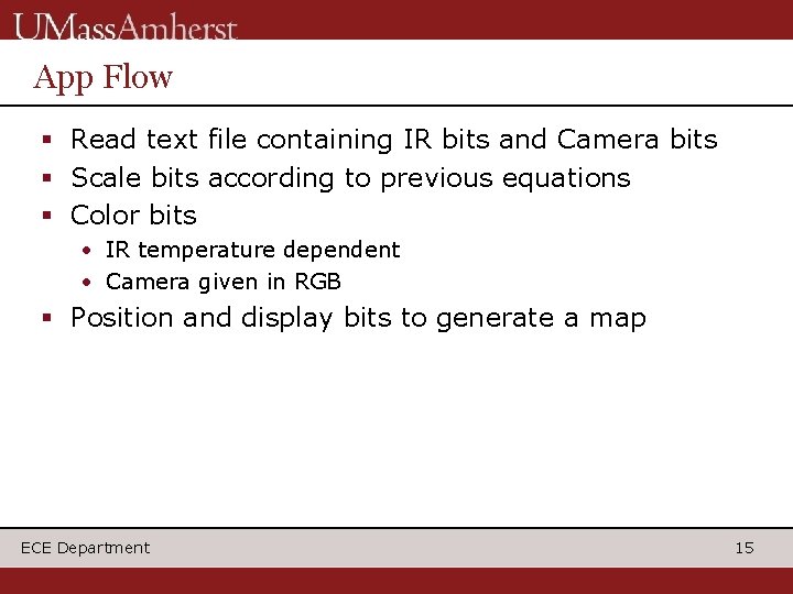
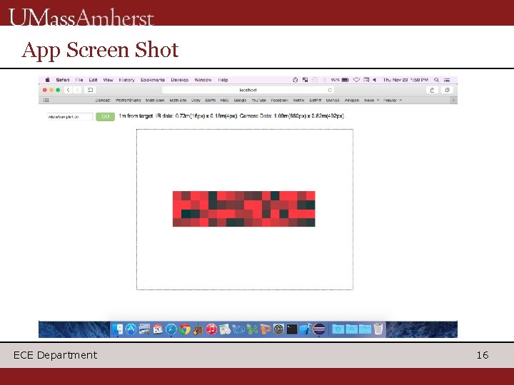
App Flow Read text file containing IR bits and Camera bits Scale bits according to previous equations Color bits • IR temperature dependent • Camera given in RGB Position and display bits to generate a map ECE Department 15
App Screen Shot ECE Department 16
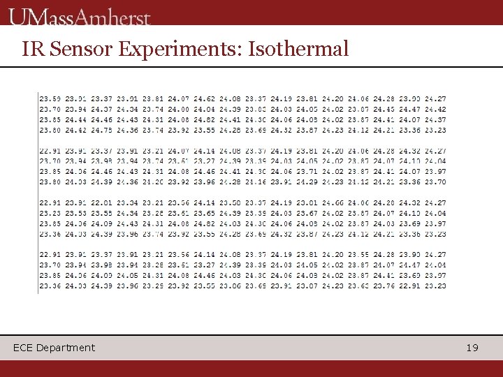
IR Sensor Specifications Store temperature array in Arduino memory for data link to access Maintain uniform values in array in isothermal environment Be able to signal copter to stop when seeing a temperature difference of 5 degrees Celsius ECE Department 17
IR Sensor Challenges Temperature fluctuations in uncontrolled environment Long duration use heats sensor skewing accuracy Larger distances increases area each pixel sees • Value is average temp of seen area ECE Department 18
IR Sensor Experiments: Isothermal ECE Department 19
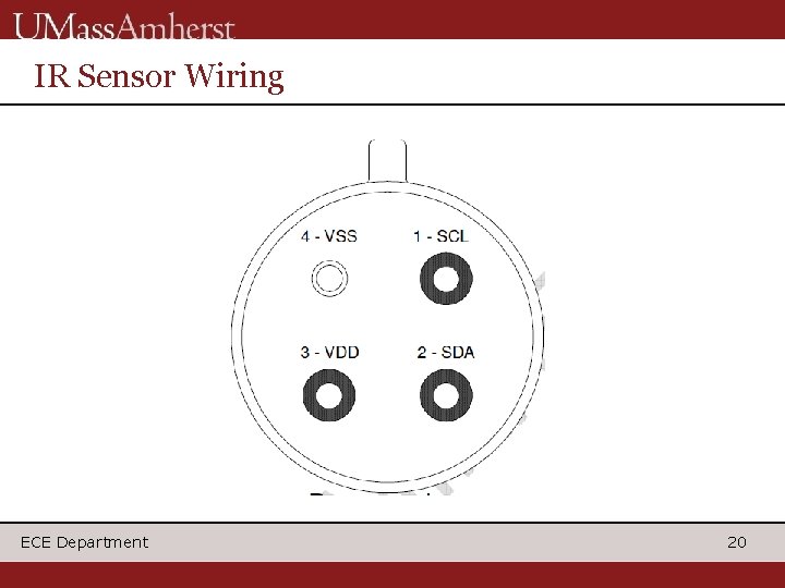
IR Sensor Wiring ECE Department 20
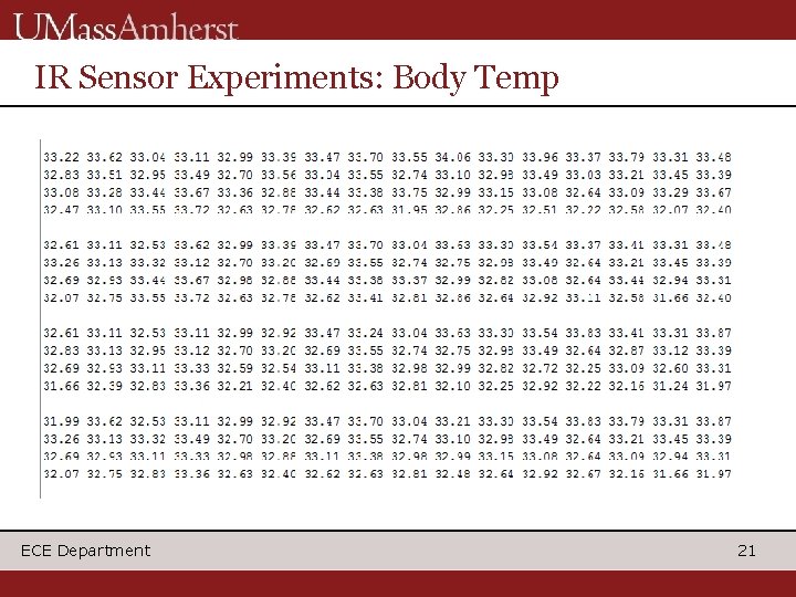
IR Sensor Experiments: Body Temp ECE Department 21
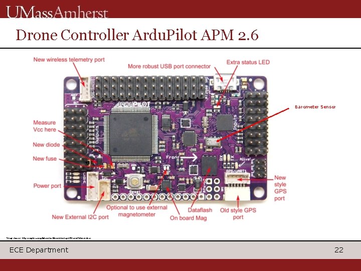
Drone Controller Ardu. Pilot APM 2. 6 Barometer Sensor Image Source: http: //copter. ardupilot. com/wiki/common-apm 25 -and-26 -overview/ ECE Department 22
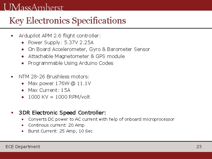
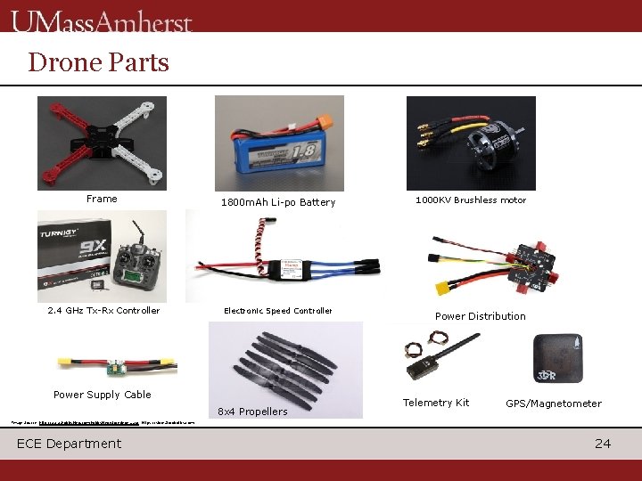
Key Electronics Specifications Ardupilot APM 2. 6 flight controller: • Power Supply: 5. 37 V 2. 25 A • On Board Accelerometer, Gyro & Barometer Sensor • Attachable Magnetometer & GPS module • Programmable Using Arduino Codes NTM 28 -26 Brushless motors: • Max power 176 W @ 11. 1 V • Max Current: 15 A • 1000 KV = 1000 RPM/volt 3 DR Electronic Speed Controller: • • • Converts DC power to AC current with help of onboard microprocessor Continous current: 20 Amp Burst Current: 25 Amp, 10 Sec ECE Department 23
Drone Parts Frame 1800 m. Ah Li-po Battery 2. 4 GHz Tx-Rx Controller Electronic Speed Controller Power Supply Cable 8 x 4 Propellers 1000 KV Brushless motor Power Distribution Telemetry Kit GPS/Magnetometer Image Source: http: //www. hobbyking. com/hobbyking/store/index. asp, https: //store. 3 drobotics. com/ ECE Department 24
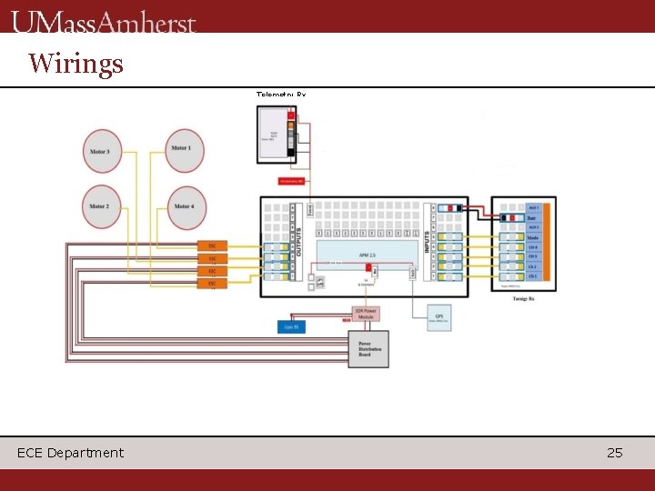
Wirings Telemetry Rx ECE Department 25
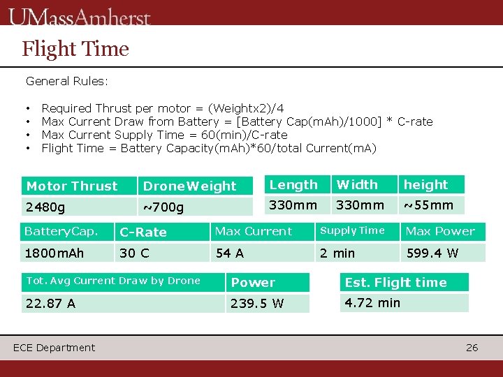
Flight Time General Rules: • • Required Thrust per motor = (Weightx 2)/4 Max Current Draw from Battery = [Battery Cap(m. Ah)/1000] * C-rate Max Current Supply Time = 60(min)/C-rate Flight Time = Battery Capacity(m. Ah)*60/total Current(m. A) Motor Thrust Drone Weight Length Width height 2480 g ~700 g 330 mm ~55 mm Battery Cap. C-Rate Max Current Supply Time Max Power 1800 m. Ah 30 C 54 A 2 min 599. 4 W Tot. Avg Current Draw by Drone Power Est. Flight time 22. 87 A 239. 5 W 4. 72 min ECE Department 26
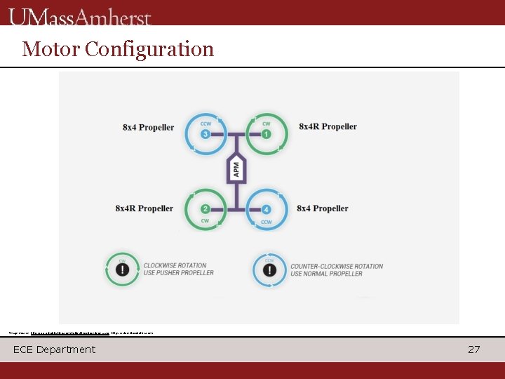
Motor Configuration Image Source: http: //www. hobbyking. com/hobbyking/store/index. asp, https: //store. 3 drobotics. com/ ECE Department 27
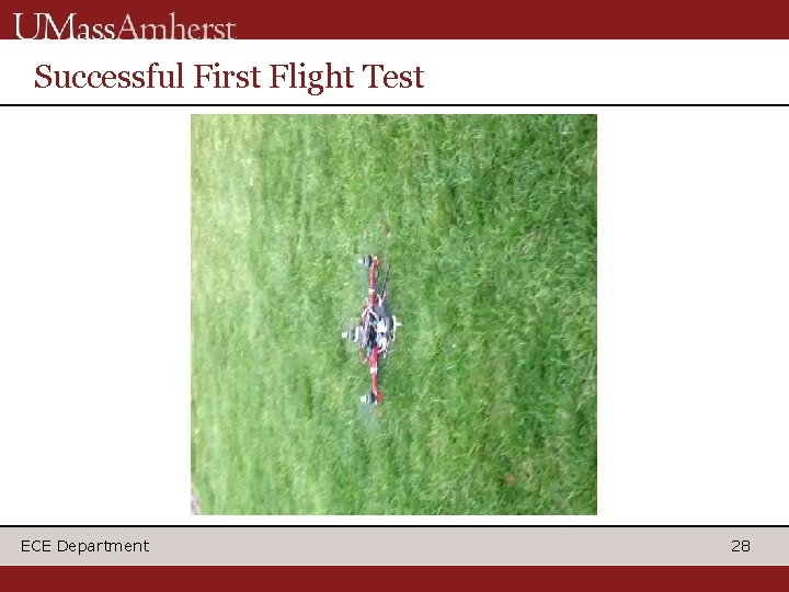
Successful First Flight Test ECE Department 28
FAA Regulations on Drones Don’t fly Maintain Don’t fly ECE Department above 400 ft within 3 mi of airport visual line of sight while airborn above populated areas 29
Accomplishments Motors and ESC are responding properly and Drone is able to fly Data communication link Web App that reads test data from a file and processes it to draw a map ECE Department 30
Proposed MDR Deliverables Web Application (core algorithms) –Stefan Totino Arduino code for I/O of the IR sensor working -Dylan Fallon Data Transmission from Radio -Jason Fellows Motor control using electronic speed controller(ESC) and 9 Do. F sensor working -Jamyang Tenzin ECE Department 31
CDR Deliverables Will optimize PID values for more stability Communications with the IR sensor for autopilot trigger will be added After autopilot trigger, the drone will hover at certain altitude to take the picture and thermal image App will be fully functional with actual data from systems components i. e. pixels and altitude readings Camera Integration ECE Department 32
References http: //copter. ardupilot. com/ http: //store. 3 drobotics. com/? utm_source=www&utm_medium=corporate+site&utm _term=store&utm_campaign=store+click+on+corporate+site http: //www. hobbyking. com/hobbyking/store/index. asp http: //www. youtube. com/watch? v=rw. Hojr. Twq 9 k https: //www. commonsenserc. com/page. php? page=c_ratings_explained. html http: //multicopter. forestblue. nl/lipo_need_calculator. html https: //ghowen. me/build-your-own-quadcopter-autopilot/ http: //diydrones. com/forum/topics/question-regarding-battery-pack-for-turnigy-9 x 2 -4 -ghz 8 ch? page=1&comment. Id=705844%3 AComment%3 A 773869&x=1#705844 Commen t 773869 https: //www. hobbyking. com/hobbyking/store/__21478__NTM_Prop_Drive_28_26_1 000 KV_235 W. html http: //www. hobbyking. com/hobbyking/store/__9369__Turnigy_1800 m. Ah_3 S_30 C_ Lipo_Pack. html https: //www. hobbyking. com/hobbyking/store/__28172__F 330_Glass_Fiber_Mini_Qu adcopter_Frame_330 mm. html ECE Department 33
References ECE Department 34