TENSILE PROPERTIES OF COMPOSITES Composite Testing in aeronautic


![strength Probability of survival • 1 0. 8 [90] 0. 6 [0/+45/90] [0] 0. strength Probability of survival • 1 0. 8 [90] 0. 6 [0/+45/90] [0] 0.](https://slidetodoc.com/presentation_image_h/2e26a1d3eb1650a865d6a50c93661ff3/image-9.jpg)


![The laminate modulus can be obtained as: [0] [0/90]S F K A 0 The laminate modulus can be obtained as: [0] [0/90]S F K A 0](https://slidetodoc.com/presentation_image_h/2e26a1d3eb1650a865d6a50c93661ff3/image-13.jpg)


- Slides: 25

TENSILE PROPERTIES OF COMPOSITES

Composite Testing in aeronautic industry

Composite Testing in aeronautic industry Primary Structures must be certified by analysis & substantiated by test evidence n. The test plan for certification will be utilizing the “Building Block” approach: - Development and validation of analysis methods and allowables - Design detail development and validation - Extend methods and allowables developed - Risk reduction for full scale certification tests The test panel simulation analysis: - Non-linear FE Models used for configuration development in failure mode analysis, bond integrity analysis, BVID (Barely Visible Impact Damage) damage analysis & environment effects analysis

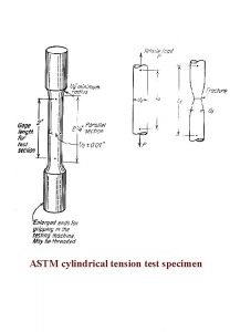
Tensile test The tensile specimen is held by grips and pulled at a recommended cross head speed of 0. 02 cm/min.

Tensile test • ASTM D 3039 -76 • Rectangular specimen • Constant cross-section • Through fillets the stress concentration is prevented by allowing the specimen to break in the middle End tab Gauge length thickness End tab width

tabs • The tabs are recommended for gripping the specimen. It protects the specimen from load being directly applied to the specimen causing the damage. Thus, the load is applied to the specimen through the grips. The tabs can be fabricated from a variety of materials, including fiberglass, copper, aluminum or the material and laminate. Further, end-tabs can also facilitate accurate alignment of the specimen in the test machine, provided that they are symmetrical and properly positioned on the specimen. The tabs are pasted to the specimen firmly with adhesive. • During tensile test, the specimen deforms both longitudinally and transversely, then the measurable stiffness are the tensile modulus E 11, E 22, and the Poisson’s ratios v 12, v 21 • In order to measure the effective deformations, two strain gauges glued on the two surfaces of the specimen, transversely and longitudinally, are used

Elastic constants- principal directions • Tests of 0° unidirectional laminate • E 11 = longitudinal modulus • v 12 = maximum Poisson’s ratio • Test of 90° unidirectional laminate • E 22 = transverse modulus • v 21 = minimum Poisson’s ratio

Elastic constants-modulus • L w
![strength Probability of survival 1 0 8 90 0 6 04590 0 0 strength Probability of survival • 1 0. 8 [90] 0. 6 [0/+45/90] [0] 0.](https://slidetodoc.com/presentation_image_h/2e26a1d3eb1650a865d6a50c93661ff3/image-9.jpg)
strength Probability of survival • 1 0. 8 [90] 0. 6 [0/+45/90] [0] 0. 4 0. 2 0 51 62 73 380 545 1020 Ultimate stress (MPa) 1475

Unidirectional laminates ØThe strength for =0° depends mainly on the fibers (it is a fiber dominated property) 1725 Boron-epoxy 1380 Ø For 0°< <90° a non linearity may occurs. Tensile stress (MPa) Ø The - curve is linear until break. Ø For =90° strength depends mainly 1 on the matrix (it is a matrix dominated property). An important role is also played by the fiber-matrix interface. 0° laminates Fiber volume fraction 0. 6 HT carbon-epoxy 1035 S glass-epoxy 690 kevlar-epoxy 345 Aluminum 7075 -T 6 0 0. 5 1 1. 5 2 2. 5 Tensile strain (%) 3. 0

Dependence of the modulus and strength on (angle ply) • Variations of tensile modulus and tensile strength of a unidirectional carbon fiber– epoxy laminate with fiber orientation angle 60 stength (MPa) Modulus (GPa) 300 200 100 0 30 60 (degrees) 40 20 90 0 30 60 (degrees) 90

Cross-Ply Laminates • Alternating laminae at 0° and 90° • Tensile Curve - can be approximated by a bilinear behaviour • The laminate behavior will undergo a change after the rupture of the laminae at 90°(brittle failure due to the matrix), evidenced by a change in the slope of the curve in correspondence of the knee • Even if laminates are made with brittle materials, they show a pseudo-ductility [0] [0/90]S F K ES E TU knee [90] LU
![The laminate modulus can be obtained as 0 090S F K A 0 The laminate modulus can be obtained as: [0] [0/90]S F K A 0](https://slidetodoc.com/presentation_image_h/2e26a1d3eb1650a865d6a50c93661ff3/image-13.jpg)
The laminate modulus can be obtained as: [0] [0/90]S F K A 0 A 90 E = E 11 + E 22 A A A 0, A 90 = area of the section ES E [90] A = total area, A 0 + A 90 knee TU LU In correspondence of the knee in the plot, the strain will correspond to the strain at break value for the lamina at 90° ( TU ), thus the corresponding strength will be: k = E TU Beyond the knee, the contribution of the laminae at 90 °to the laminate stiffness can be neglected and then the new modulus and the ultimate strength are obtained as: A 0 Es = E 11 A F = k + Es ( LU – TU)

Progressive failure • C L K B D A

Multidirectional Laminates • Tensile stress–strain curves for laminates containing • • • (MPa) • different fiber orientations in different laminas are in general nonlinear. These curves are approximated by a number of linear portions that have different slopes. The first knee in these diagrams is called the first ply failure (FPF) point. Many laminates retain a significant load-carrying capacity beyond the FPF point, but for some laminates with high notch sensitivity, failure occurs just after FPF Furthermore, cracks appearing at the FPF may increase the possibility of environmental damage (such as moisture pickup ) as well as fatigue failure. • The FPF point has special importance in many laminate designs. 1104 828 [0/+45]S [0/+45/90]S 552 276 [+45/90]S 0 2 4 6 (*10 -6)

Multidirectional Laminates • Tensile stress–strain curves for laminates containing different fiber orientations in different laminas are in general nonlinear. Note the effect of a more deformable matrix

ANGLE PLY LAMINATES • close to 0° Stiffening of the material with an increase of the modulus with the load due to a tendency of the fibers to align in the load direction • Stiffening laminates do not exhibit residual strain on unloading. close to 90° Decreased modulus growth due to shear stress • They exhibit a residual strain on unloading and a hysteresis loop on reloading. • However, the slope of the stress–strain curve during reloading does not change from the slope of the original stress– strain curve.

Woven fabric laminates They are mainly used to provide properties that are more balanced in the 0° and 90° directions than unidirectional laminates. The tensile strength and modulus of a woven fabric laminate are, in general , lower than those of multilayered laminates. The principal reason is the presence of fiber undulation as the fiber yarns in the fill direction cross over and under the fiber yarns in the warp direction to create an inter locked structure. Under tensile loading , these crimped fibers tend to straighten out, which creates high stresses in the matrix. As a result, micro -cracks are formed in the matrix at relatively low loads. This is also evidenced by the appearance of one or more knees in the stress–strain diagrams

Sheet Molding Compounds (SMC) • SMC composites exhibit isotropic properties in the plane of the laminate; • The knee in the stress train diagram corresponds to the development of craze marks • • in the specimen. At higher loads, the density of craze marks increases until failure occurs by tensile cracking in the matrix and fiber pullout. Both tensile strength and tensile modulus increase with fiber volume fraction. The stress at the knee is nearly independent of fiber volume fractions The strain at the knee is nearly equal to the matrix failure strain.

SMC-R with glass fiber SMC-R isotropic properties in the laminate plane The highlighted knee in the diagram denote the presence of cracks that, by increasing the load, increase their number up to the final fracture of the composite

Compressive properties • Compressive properties of thin composite laminates are difficult to measure owing to sidewise buckling of specimens. A number of test methods and specimen designs have been developed to overcome the buckling problem • Celanese tests and other rmodifications

Flexural properties • Flexural properties, such as flexural strength and modulus, are determined by • • ASTM test method D 790. In this test, a composite beam specimen of rectangular cross section is loaded in either a three-point bending mode or a four-point bending mode In either mode, a large span–thickness (L=h) ratio is recommended. The maximum fiber stress at failure on the tension side of a flexural specimen is considered the flexural strength of the material. Using a homogeneous beam theory, the flexural strength and modulus in a threepoint flexural test is given by: • m is the initial slope of the load–deflect ion curve.

Flexural properties • How ever, the following limitations of three- point flexural tests should be recognized: • The maxi mum fiber stress may not always ocur at the outermost layer in a composite laminate. Thus, for more accurate values, lamination theory should be employed • Both normal stress and shear stress are present throughout the beam span. Due to the relatively high Ex/G ratios, shear strains can be quite relevant, and can be reduced by using high L/d • The flexural modulus is a critical function of the lamina stacking sequence, and therefore, it doe s not always correlate with the tensile modulus, which is less dependent on the stacking sequence.

In-plane shear properties •

Interlaminar shera stress • Interlaminar shear strength (ILSS) refers to the shear strength parallel to the plane of lamination. • It is measured in a short-beam shear test in accordance with ASTM D 2344. • A flexural specimen of small span–depth (L=h) ratio is tested in three-point bending to produce a horizontal shear failure between the laminas. • Thus , for sufficiently small L/h (4 or 5) ratios, the maximum shear stress in the beam will reach the ILSS of the material even though the maximum normal stress is still quite low. • The beam will fail in the interlaminar shear mode by cracking along a horizontal plane between the laminas
 Astm d7332
 Douglas fir elastic modulus
 Fishing line tensile strength
 Tensile strength formula
 Yield and tensile strength
 Engineering stress
 Crostalline
 Tensile test simulation
 Tensile test cylindrical specimen
 Tensile strength of spaghetti
 Split tensile strength of concrete can be calculated as
 Tensile strength of amalgam
 Sports medicine taping techniques
 Tensile stress
 Tensile strength
 Micro tensile tester
 Ceramic matrix composites definition
 Orthotropic compliance matrix
 Composite and component knowledge ofsted
 Composite resin definition
 Matrix phase meaning
 Ceramic matrix composites definition
 Brandy dantzler
 Esz zrt
 Maine marine composites
 Composite manufacturing process
