Mechanical Testing of Composites and their Constituents Tests

 Standards • Test standards for polymer matrix")

 Different ways of")
.")

 ASTM D 638 -10")

 Neat resin")


 Specimen geometry")


")
 test")


 Rail")
")


 test for Mode I and Mode II delamination testing (ASTM")


 Strain gage Strain, ε Test specimen Creep")

 is the creep compliance, S 0")


")


")


- Slides: 73
Mechanical Testing of Composites and their Constituents • Tests done to determine intrinsic material properties such as modulus and strength for use in design and analysis (major emphasis here) • Tests done to determine quality or acceptability of specific components during manufacturing (minor emphasis here)
American Society for Testing and Materials (ASTM) Standards • Test standards for polymer matrix and metal matrix composites - ASTM Vol. 15. 03 Space Simulation; Aerospace and Aircraft; Composite Materials • Test standards for ceramic matrix composites – ASTM Vol. 15. 01 – Refractories; Activated Carbon; Advanced Ceramics
TM HI-NICALON Type S CERAMIC FIBER
Direct measurement of fiber longitudinal properties Ef 1 and Sf 1(+) Different ways of mounting fiber specimens on backing strip. (From ASTM Standard C 1557 -03 R 08. Copyright ASTM International. With permission. )
Different failure modes for resin-impregnated strand test specimens. (From ASTM Standard D 4018 -99(2008). Copyright ASTM International. Reprinted with permission. )
Indirect measurement of fiber transverse modulus Ef 2 P = load P Prediction Experimental data Δ Δ = deflection Diametral compression of fiber for measurement of fiber transverse Young’s modulus. (From Kawabata, S. 1989. In Vinson, J. R. ed. , Proceedings of the 4 th Japan–U. S. Conference on Composite Materials, pp. 253– 262. CRC Press, Boca Raton, FL. With permission. )
Tensile measurement of neat resin properties Em and Sm 1(+) ASTM D 638 -10 Type I, III, IV and V neat resin tensile specimen geometries. (From ASTM Standard D 638 -10. Copyright ASTM International. Reprinted with permission).
ASTM 618 -05 Conditioning Plastics and Electrical Insulating Materials for Testing Standard Laboratory Atmosphere: Temperature of 23 C (73. 4 F) and relative humidity of 50%
Specimen for measurement of neat resin compressive properties Em and Sm 1(-) Neat resin compressive test specimen. (From ASTM Standard D 695 -10. Copyright ASTM International. Reprinted with permission. )
Neat resin compression specimen support jig Support jig for D 695 -10 compressive test specimen. (From ASTM Standard D 695 -02 a. Copyright ASTM International. Reprinted with permission. )
Compression test fixture for neat resin specimen Compression fixture with ball-and-socket joint to minimize bending. (From ASTM Standard D 695 -10. Copyright ASTM International. Reprinted with permission. )
Three-point bending specimen for flexural properties of neat resin or composite. (From ASTM Standard D 790 -10. Copyright ASTM International. Reprinted with permission. ) M Bending moment diagram
Constituent Volume Fraction Measurement • Removal of resin matrix from composite sample by either chemical digestion with acids or other chemicals (carbon fiber composites), or resin burn -off in a furnace (glass fiber composites) according to ASTM Standard D 3171 -09 • Computer-aided image analysis of digital photomicrographs to determine fiber area fractions of polished composite specimens
Composite tensile specimen for measurement of longitudinal properties E 1 and SL(+) Specimen geometry for ASTM D 3039/D 3039 M-08 standard tensile test. (Dimensions from ASTM D 3039/D 3039 M-08. Copyright ASTM International. Reprinted with permission. )
Typical stress-strain curves from D 3039 specimen Longitudinal and transverse strain data at different stresses for [0]8 graphite/epoxy tensile specimen. (From Carlsson, L. A. and Pipes, R. B. 1989. Experimental Characterization of Advanced Composite Materials. Prentice-Hall, Inc. , Englewood Cliffs, NJ. Reprinted by permission of Prentice-Hall, Englewood Cliffs, NJ. )
End constraints can cause bending of off-axis tensile specimens due to shear coupling Effect of end conditions on deformation of an off-axis tensile specimen exhibiting shear coupling. (From Pagano, N. J. and Halpin, J. C 1968. Journal of Composite Materials, 2, 18– 31. With permission. )
Importance of specimen length-to-width ratio
Variation of “apparent moduli” and with fiber orientation for off-axis tensile test of a unidirectional T 300/934 carbon/epoxy lamina. Lamina engineering constants are taken from Table 2. 2. Conclusion: except at
Lamina tensile strength can be “backed out” from laminate tensile test data “Backed out” tensile strength data from seven different laminates of IM 7 G/8551 -7 graphite/epoxy. (From Rawlinson, R. A. 1991. Proceedings of the 36 th International SAMPE Symposium and Exhibition, Book 1, pp. 1058– 1068. Reprinted by permission of the Society for the Advancement of Material and Process Engineering. )
Compression test specimen for ASTM D 3410/D 3410 M-03 D 3410 fixtures produce side-loading rather than end-loading as in D 695 Geometry for tabbed compression test specimen. (From ASTM Standard D 3410/D 3410 M-03 (Reapproved 2008). Copyright ASTM International. Reprinted with permission. )
Cutaway view of compression test fixture for ASTM D 3410/D 3410 M-03 Cross-section view of ASTM D 3410/D 3410 M-03 (Reapproved 2008) compression test fixture. (From ASTM Standard D 3410/D 3410 M-03 (Reapproved 2008). Copyright ASTM International. Reprinted with permission. )
Sandwich beam specimen for face sheet compression ASTM D 5467/D 5467 M-97 (Reapproved 2004) sandwich beam specimen for face sheet compression. (From ASTM Standard D 5467/D 5467 M-97 (Reapproved 2004). Copyright ASTM International. Reprinted with permission. )
Test fixture for ASTM D 6641/D 6641 M- 09 combined loading compression (CLC) test method Test fixture for ASTM D 6641/D 6641 M-09 CLC test method. (From ASTM Standard D 6641/D 6641 M-09. Copyright ASTM International. Reprinted with permission. )
Test fixture for compressive residual strength of polymer composite plates. (From ASTM D 7137/D 7137 M-07) Test fixture for compressive residual strength of polymer composite plates. (From ASTM D 7137/D 7137 M-07. Copyright ASTM International. Reprinted with permission. )
Comparison of shear test methods for composites. (From Adams, D. F. , 2005 High Performance Composites, 13(5), pp. 9– 10)
Iosipescu test fixture for shear strength and stiffness in all three shear stress states (ASTM D 5379)
Test fixture for V-notched rail shear test. (From ASTM Standard D 7078/D 7078 M-05. Copyright ASTM International. Reprinted with permission. )
Different test specimen arrangements for V-notched rail shear test. (From ASTM Standard D 7078/D 7078 M-05. Copyright ASTM International. Reprinted with permission. )
Rail shear test fixtures, ASTM D 4255/D 4255 M-01 (Methods A and B) Rail shear test fixtures. (From ASTM Standard D 4255/D 4255 M-01(2007). Copyright ASTM. Reprinted with permission. )
Analysis of Rail Shear Test Procedure A Shear stress along loading axes x, y) (10. 8) Strain transformation from normal strain along strain gage axis x’ oriented at 45 o from x to shear strain along (x, y) axes (10. 10)
Therefore the shear modulus along loading axes is where P, L, t, and εx’ are all measured quantities. If the specimen is unidirectional, and (x, y) are aligned with (1, 2), then and if this specimen is loaded to failure
Laminate test for in-plane shear modulus G 12 Shear stress from applied stress: Shear strain from measured normal strains: Shear modulus:
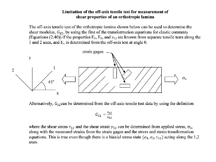
Off-axis tensile test for indirect measurement of G 12 Young’s modulus, Ex 2 When y x 1 (2. 39) or (2. 40)
Off-axis tensile test for indirect measurement of G 12 • Conduct off-axis tensile test to measure Ex at some fiber orientation θ • Conduct longitudinal tension test to measure E 1 and υ12 • Conduct transverse tension test to measure E 2 • Use above results in Eq. 2. 40 to calculate G 12
ASTM D 2344/D 2344 M-00 Short beam shear test for interlaminar strength (parallel fibers only) Note: not recommended for measurement of intrinsic properties, only for quality control and specification
Short beam test specimen with shear and moment diagrams Mechanics of materials stresses Shear stress Bending stress
Short beam shear test • Short beam fails due to interlaminar shear stress • Long beam fails due to either tensile or compressive normal stress on bottom or top of beam, respectively • Questions about accuracy of mechanics of materials beam theory equations for stresses in short beams where support effects may not be negligible (Whitney’s theory of elasticity analysis)
Whitney’s conclusion: Stress distributions from mechanics of materials beam theory are only accurate far away from loads and supports Comparison of predicted interlaminar shear stress distributions from theory of elasticity (solid curves) and beam theory (dotted curve) for a 50 ply short beam shear specimen with length-to-depth ratio of 4. Differences are particularly large near loading point (section C) and support points (section A). (From Whitney, J. M. 1985. Composites Science and Technology, 22, 167 -184. With permission)
Interlaminar Fracture Tests
DCB analysis – treat one half of DCB as cantilever beam (ASTM D 5528 -01 (2007)e 3) Mode I strain energy release rate (10. 16)
Mixed mode bending (MMB) test for Mode I and Mode II delamination testing (ASTM Standard D 6671) Test fixture for MMB test. (From ASTM Standard D 6671/D 6671 M-06. Copyright ASTM International. Reprinted with permission. )
Single fiber fragmentation specimen for measurement of fiber/matrix interfacial shear strength Test procedure: Load specimen until fiber starts to break up into fragments, then measure “critical lengths” of fragments, then calculate interfacial shear strength from theory of discontinuous fiber composites developed in Chap. 6 Single-fiber fragmentation specimen developed by Drzal et al. (From Drzal, L. T. , Rich, M. J. , and Lloyd, P. F. 1982. Journal of Adhesion, 16, 1– 30. ; Drzal, L. T. , Rich, M. J. , Koenig, M. F. , and Lloyd, P. F. 1983. Journal of Adhesion 16, 133– 152. With permission. )
Microindenter test for fiber/matrix interfacial shear strength Test procedure: Load end of fiber in compression with microindenter probe until fiber slips with respect to matrix, then use finite element analysis of specimen to estimatefiber/matrix interfacial shear strength Microindenter test for fiber/matrix interfacial strength. (From Mandell, J. F. , Grande, D. H. , Tsiang, T. H. , and Mc. Garry, F. J. 1986. Composite Materials: Testing and Design (Seventh Conference), ASTM STP 893, pp. 87– 108. American Society for Testing and Materials, Philadelphia, PA. Copyright ASTM. Reprinted with permission. )
Microbond test for fiber/matrix interfacial shear strength resin droplet fiber embedded in resin droplet applied tensile force Problem: Difficult to reproduce the composite resin matrix cure condition in a small droplet.
Source: From Mc. Donough, W. G. , Herrera-Franco, P. J. , Wu, W. L. , Drzal, L. T. , and Hunston, D. L. 1991. In Advanced Materials/Affordable Processes, Proceedings of 23 rd International SAMPE Technical Conference, Kiamesha Lake, NY, pp. 247– 258. Society for Advancement of Material and Process Engineering, Covina, CA. Reprinted by permission of the Society for the Advancement of Material and Process Engineering.
ASTM D 5766 open hole tension test – similar to ASTM D 3039 tensile test, but with central hole Acceptable test failure modes for ASTM D 5766/D 5766 M-07 standard test method for open hole tensile strength (a) failure mode codes (b) LGM (c) AGM (d) MGM. (From ASTM D 5766/D 5766 M-07. 2009. Copyright ASTM International. Reprinted with permission. )
ASTM D 5961 bearing test – Procedure A Fixture assembly for ASTM D 5961/D 5961 M-08 (Procedure A) double shear test method for bearing response of polymer matrix composite laminates. (From ASTM D 5961/D 5961 M-08. 2009. Copyright ASTM International. Reprinted with permission. )
ASTM D 7332 fastener pull-through test Test fixture and specimen for ASTM standard test method for measuring the fastener pull-through resistance of a fiber-reinforced polymer matrix composite, Procedure B. (From ASTM D 7332/D 7332 M-07 e 1. Copyright ASTM International. Reprinted with permission. )
Measurement of Viscoelastic and Dynamic Properties
Creep test parameters Total strain = εo+ε(t) Strain gage Strain, ε Test specimen Creep strain, ε(t) Initial elastic strain, εo Time, t Constant applied stress, σo Elastic compliance = εo/ σo Creep compliance = ε(t)/σo
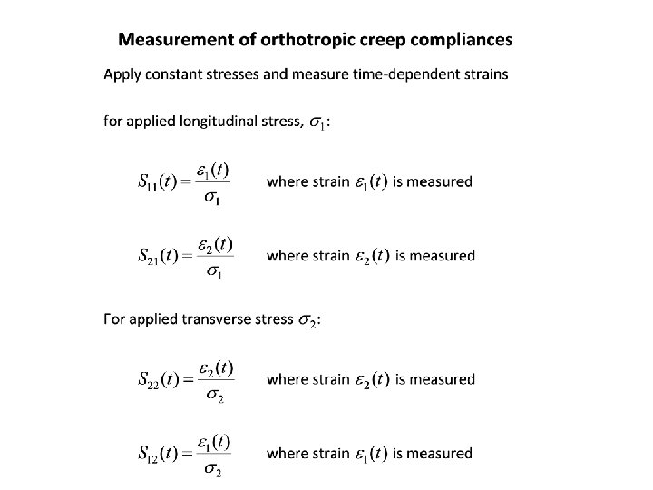
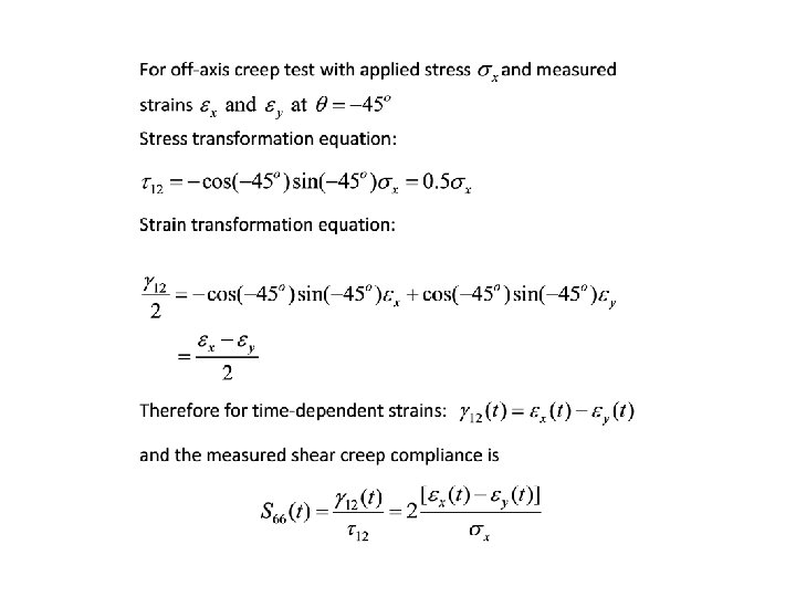
Measurement of orthotropic creep compliances
Empirical power law for creep compliance where S(t) is the creep compliance, S 0 the initial elastic compliance, and S 1 and n the empirically determined parameters
Important modes of specimen deformation for vibration tests Flexural Torsional Longitudinal
Natural frequencies of flexural and torsional modes of vibration are usually in the range of typical excitation frequencies, but longitudinal modes are usually well above this range. Automated Dynamic Mechanical Analyzers (DMA) typically operate in the flexural mode. Range of typical excitation frequencies Longitudinal modes Response Flexural and torsional modes Frequency
Representation of automated DMA plot showing storage modulus, loss modulus and loss factor (tan δ) vs. temperature.
Material Damping • Energy dissipation within a material under cyclic or oscillatory stress • Characterized by stress-strain hysteresis loop under steady-state vibration and decaying oscillation under free vibration • Area enclosed by hysteresis loop and rate of decay are proportional to damping factor • Damping is linear if it is independent of oscillation amplitude Hysteresis loop in steady state vibration Free vibration decay
Complex modulus of linear viscoelastic material from stressstrain hysteresis loop ( assuming perfectly elliptical loop) Energy dissipated per cycle Energy stored at maximum displacement Loss factor Storage Modulus
Free vibration decay method Logarithmic decrement Loss factor (for light damping)
Impulse-frequency response method Impulse-frequency response apparatus for flexural vibration of cantilever beam specimens
Modal frequencies and loss factors found by curve-fitting to frequency response curve at peak frequencies
Single Degree of Freedom Curve Fit to Peak in Frequency Response Curve by Half Power Bandwidth Method Amplitude Peak for nth mode X 0. 707 X Frequency Damping Loss Factor = natural frequency of nth mode = bandwidth at half power points (10. 36)
Measurement of Hygrothermal Properties
Measurement of glass transition temperature, Tg ASTM D 7028 -07 e 1 test for determination of DMA Tg from storage modulus vs. temperature plot
ASTM 696 -08 test for measurement of coefficient of thermal expansion, CTE Measure thermal strain, , or the change in length, , of a specimen of original length which is subjected to a temperature change in an environmental chamber Measured coefficient of thermal expansion is (10. 37)
Variation of measured longitudinal and transverse thermal strains for unidirectional Kevlar 49/epoxy and S-glass/epoxy with temperature. (From Adams, D. F. , Carlsson, L. A. , and Pipes, R. B. , 2003. Experimental Characterization of Advanced Composite Materials. CRC Press, Boca Raton, FL. With permission. )
Measured CTEs for undirectional orthotropic lamina Measured longitudinal CTE Measured transverse CTE
ASTM D 5229 test for measurement of moisture absorption properties Through-thickness Diffusivity (10. 40)
Example of test done to determine quality or acceptability of specific components during manufacturing ASTM D 2290 Split Disk Test for tensile strength of filamentwound composite rings
Exploded view of test fixture for ASTM D 2290 Split Disk Test for Rings