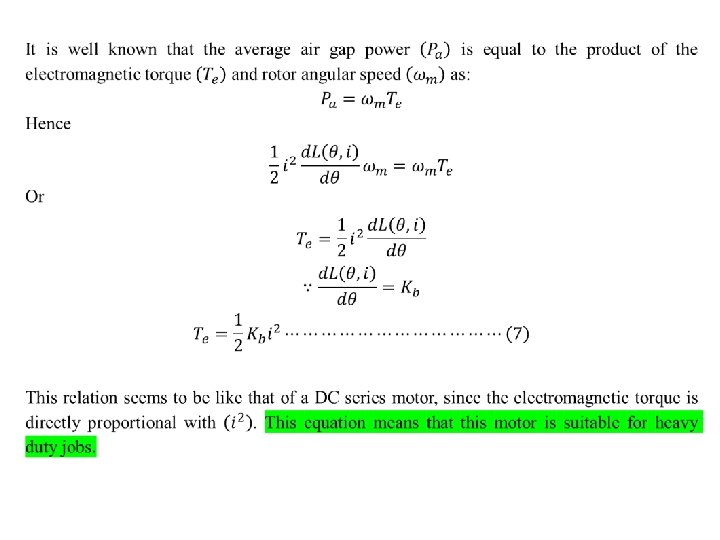
Speed Torque Characteristics of Reluctance Motor The starting

 Cross-section of switched reluctance machine with 6 stator and")
 shown")
")
 Rotor rotation as switching sequence proceeds in a three phase SRM, the")
")
 Note 1: The SRM cannot operate without a driver shown in Fig.")
 A SRM of (12/8) pole")
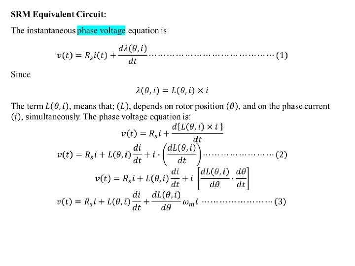
 SRM equivalent circuit.")
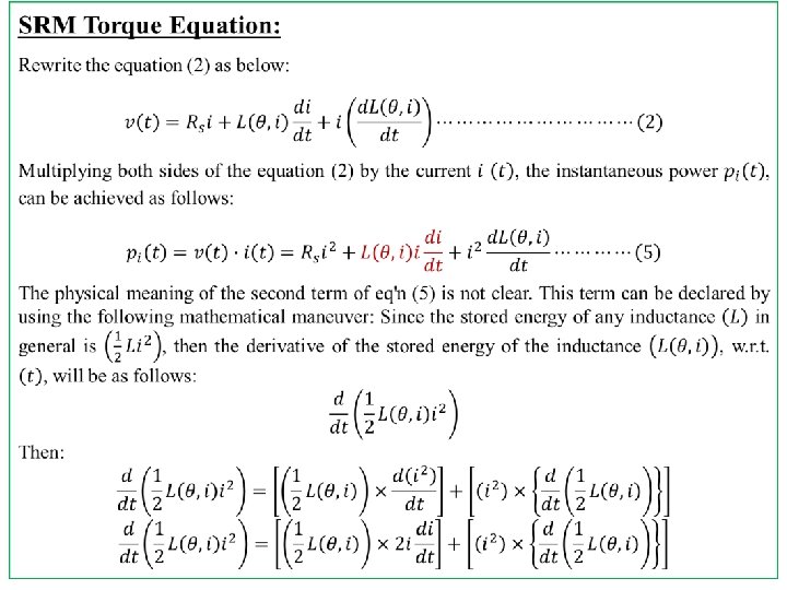
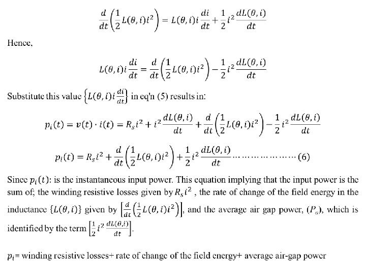
 Input power Power of the magnetic field (Imaginary Power) Electromagnetic")
- Slides: 14
Speed Torque Characteristics of Reluctance Motor The starting torque of the reluctance motor depends upon position of rotor because the rotor is a salient pole one. The value of starting torque lies between 300 to 400 percent of its full load torque. Reluctance motors are subjected to cogging at the time of starting. Cogging is the locking tendency of the rotor which can be minimized by skewing the rotor bars and not making the number of rotor slots equal to an exact multiple of the number of poles.
Switched Reluctance Motor Fig. (11) Cross-section of switched reluctance machine with 6 stator and 4 rotor poles. Notice the concentrated windings on the stator poles.
Working of SRM Since 1969, a variable reluctance motor (or switched reluctance motor) shown in fig. (11), has been proposed for variable speed applications due to the “reinvention” and the advent of inexpensive high-power switching devices. Even though this machine is a type of synchronous machine, it has certain novel features. It has wound field coils of a DC motor for its stator windings and has no coils or magnets on its rotor. Both the stator and rotor have salient poles, hence the machine is referred to as a doubly salient machine.
Figure (12)
Figure (13) Rotor rotation as switching sequence proceeds in a three phase SRM, the rotation direction is opposite to the direction of the excited phase. The switching angle for the phase current is controlled and synchronized with the rotor position, usually by means of a shaft position sensor.
Figure (14)
Figure (15) Note 1: The SRM cannot operate without a driver shown in Fig. (15) and without rotor position sensor. Note 2: It cannot rotate freely when it is disconnected from the power supply due to the residual magnetization in its salient poles
Figure (16) A SRM of (12/8) pole
Figure (17) SRM equivalent circuit.
Copper losses (Real power) Input power Power of the magnetic field (Imaginary Power) Electromagnetic power transferred through the air gap to a mechanical form (Real power) (Pa)