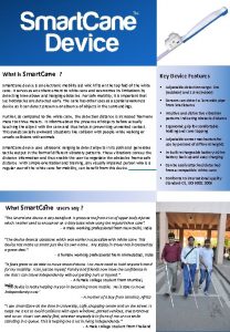
Smart Cane P 14043 Systems Design Review Lauren


- Slides: 27

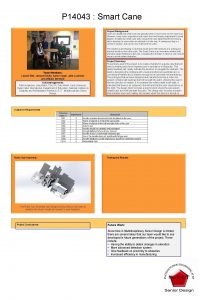
Smart Cane – P 14043 Systems Design Review Lauren Bell, Jessica Davila, Jake Luckman, William Mc. Intyre, Aaron Vogel

Agenda • Project Background • Customer Requirements • Engineering Requirements • • Functional Decomposition Concept Generation [Morph chart and Pugh charts] Concept Selection Engineering Analysis Risk Assessment Test Plan Project Plan

Why Design a Smart Cane? Conventional White Cane Advantages Inexpensive and available Disadvantages Slow navigation – user must guide himself/herself Little/no training User can “feel” the environment Guide Animals Advantages Disadvantages Takes commands Expensive Detects overhanging and tricky obstacles Can get sick/hurt Guides user Training for animal and user Long waiting lists Sometimes not allowed (illegally) in some situations User cannot “feel” environment

Ultimate Vision of Smart Cane Combined Advantages Less expensive than guide animal, available, easily replaceable Little/no training User can still “feel” the environment Guides the user (haptic feedback) Capable of detecting objects not easily felt through conventional cane Longer range beyond cane tip Possibility to integrate with other navigation technologies (GPS, stored paths, maps, etc…)

For Our Project… Our project will focus on these areas: Smart Cane Combined Advantages Less expensive than guide animal, available, easily replaceable Little/no training User can still “feel” the environment Guides the user (haptic feedback) Capable of detecting objects not easily felt through conventional cane Longer range beyond cane tip Possibility to integrate with other navigation technologies (GPS, stored paths, maps, etc…) Future projects will continue towards final Smart Cane vision…

Customer Requirements • Since Problem Definition Review • Emphasis on the haptic handle • Less emphasis on detection system • (Make it basic, detect lower-front objects, leave for future projects) • Future projects: • • Detection System Resembles a conventional cane Operated like conventional cane Improving battery life, robustness, use in other environments etc…

Engineering Requirements Revised, concise specs: • Cane characteristics • Moment of Inertia • Spring Constant • Handle diameter • Length

Concept Generation

Functional Decomposition

Morph Chart

Cane Structure – Pugh Chart Plastic Wood Aluminum Fiberglass Carbon fiber Low Density S S - Datum + Transmits vibrations/sound - + + Datum S Corrosion Resistant S - S Datum S Low Cost + + - Datum - Ease to work with and modify + S S Datum S Safe for use S - S Datum S + 2 2 1 1 - 1 2 2 1

Concept Selection – Handle*

Attractive/Repulsive Magnetism Navigation Pros • Easier to feel direction • Better directional feedback • Can be used with gloves Screw-in cap Battery housing Microcontroller Cons • Possible power limitations • No indication of proximity (acting alone) Wire windings with ferrous cores

Piston Navigation Screw-in cap Pros • Easier to feel direction • Better directional feedback • Can be used with gloves Cons • Heavier • No indication of proximity (acting alone) • May inhibit index finger haptic ability Standard servo Battery Housing Push piston Drive shaft Microcontroller

Scroll Navigation Pros • Easier to feel direction • Better directional feedback • Can be used with gloves Screw-in cap Battery Housing Microcontroller Continuous servo Cons • May inhibit index finger haptic ability Scroll Transmission

Track Ball Navigation Pros • Easier to feel direction • Better directional feedback • Can be used with gloves Cons • Heavier • Less compact Track ball • May inhibit index finger haptic ability Screw-in cap Microcontroller Battery Housing Continuous servos & transmission shafts

Torque Handle Navigation Pros • Easier to feel direction • Better directional feedback • Can be used with gloves Cons • Heavier • Moment of inertia/torque concern Screw-in cap Transmission Standard servo Microcontroller Battery housing

Handle Feedback – Pugh Chart Handle Vibration Navigation by Expansion by Motors Track ball Push Cylinders Ring attached to Handle a motors to Electromagnets move Twist via Expansion by Thermoelectric control finger Torque Electroactive /Heat in handle finger/Rotating direction Motors Polymers band that slides across finger Easy to Feel Direction Datum + + + + Provides Directional Feedback Datum + + + + Safe to use Datum S S - S S Compact Design Datum - S S - - S S Lightweight Datum - - - S S Affordable within our budget Datum S S S - S S S Fast Response time Datum S S S - - S S Easy for users to learn within our time frame Datum S S S - S S S Able to be used with gloves Datum + + - + + Indicates proximity Datum S - - S S + 3 3 2 3 3 - 2 2 1 6 3 0 0

Detection System – Pugh Chart Ultrasonic Sensor Infrared sensor Radar System w Accelerometer Image Processing Laser Light Weight Datum - S S Power Consumption Datum - + S - - Gives good signal for range Datum S - - S S Sensitive to Objects close/far away Datum S - - S S Fast Response time Datum - S S - + Durable Datum S + - S S Small in size Datum S + S S - Able to detect all objects Datum S - - + - Cost Datum S S S - - Easily Senses object location Datum + - S S - + 1 3 0 1 0 - 3 3 4

Engineering Analysis • Microcontroller • Magnets • Servo Motors • Batteries • • • Power Operating Conditions CPU Speed I/O Characteristics Torque Weight Dimensions RPM Tolerance/Precision Power Continuous/Standard • • Forces Weight Dimensions Power Heat Battery Life Power Rechargeable vs. Disposable • Size • •

Risk Assessment Importance Risk Likelihood Severity 6 Burning out micro controller 3 2 6 Software is ineffective 2 3 6 Haptic handle and detection systems integration issues 2 3 6 Not meeting customer expectations 2 3 4 Not obtaining parts on time 2 2 4 Battery malfunction 2 2 4 Over budget 2 2 3 Cane does not stay together, durability failure 1 3 3 Not completing software component 1 3 3 Haptic forces not being strong enough 1 3 3 Hardware and software integration 1 3 3 Detection is ineffective 1 3 3 Uncoordinated team schedules 3 1 3 Team Member leaves team 1 3 3 Cane gets dropped repeatedly on the ground 1 3 3 Excessive tapping 1 3 1 System is too heavy for desired cane weight 1 1 27 43 64 TOTAL

Test Plan • User Test • Battery Test • Physical Characteristics • Detection System Test

Project Plan Problem Definition • Problem Statement • Customer Requirements • Engineering Requirements System Design • Benchmarking • Functional Decomposition • Concept Generation • Risk Assessment • Test Plan • Engineering Analysis • Concept Selection Subsystem Design Detailed Design Completed Design • Proof of • Hardware and • Completed Concept Software Design • Subsystem • Updated Risk • Assembly Decompositions Assessment Process • Subsystem • Updated Test • BOM Design and Plan • Budget POs Analysis • Test Plan • Updated Risk Assessment

Three Week Plan Sunday 9/29 Monday 9/30 Tuesday 10/1 Wednesday Thursday 10/2 Friday 10/3 10/4 Systems Design Review Saturday 10/5 Engineering Analysis 10/6 10/7 10/8 10/9 Select Concept 10/10 10/11 10/12 Subsystem Decomposition/Analysis Engineering Analysis Proof of Concept 10/13 10/14 10/15 10/16 10/17 10/18 10/19 Subsystem Design Subsystem Decomposition/ Analysis 10/20 10/21 10/22 Update Test Plan and Risk Assessment 10/23 10/24 10/25 Sub Systems Design Review Update Test Plan and Risk Assessment 10/26

Questions?


Project Plan
 Tiloma cane
 Cane pruning
 Decubito a cane di fucile meningite
 Demineralization process
 Riproduzione del cane scuola elementare
 Forma attiva a passiva
 Le 10 preghiere del cane
 Testo descrittivo sulla pizza
 Eterotopia dentale
 Tongue twister christmas
 Roy calne
 Sugar cane alley analysis
 Terza declinazione secondo gruppo
 Cantotomia laterale
 Razze di csni
 Cane di fucile
 Tangram cane
 Dinamismo di un cane al guinzaglio
 Evaporated cane juice
 Limitade
 Crampo rotuleo cane
 Periodi sensibili cane
 Cane morsicatore normativa
 Bilirubinuria cause
 Ciappi cane
 Street smarts vs book smarts
 One smart man he felt smart
 It is not how smart you are it's how you are smart
