Radio Signals Modulation Defined The purpose of radio


- Slides: 19

Radio Signals

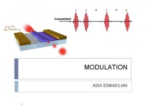
Modulation Defined • The purpose of radio communications is to transfer information from one point to another. • The information to be sent is combined with a radio wave (the carrier wave). – This process is called modulation. • The carrier wave (with the embedded intelligence) is then transmitted into space by the transmitting equipment.

Carrier and Intelligence

0% Modulation (CW)

25% Modulation

50% Modulation

100% Modulation

Over Modulation Causes Distortion

Demodulation Defined • Once the carrier wave is received, the carrier has done its job. • The carrier and intelligence are then separated (demodulation) and the carrier is discarded. • The intelligence is then processed and provided to the listener as audio, video or text.

Modulated Carrier (blue) and Original Intelligence (red)

Carrier Removed (blue) Compared to Original Intelligence (red) – Demodulated Signal

Recovered Intelligence (blue) Filtering required to remove as much carrier as possible

Major Modulation Modes • • • AM – amplitude modulation SSB – single sideband FM – frequency modulation CW – turn carrier on and off (Morse code) FSK – frequency shift keying PSK – phase shift keying

Bandwidth • Sending intelligence via a radio carrier wave takes spectrum space – called bandwidth. • As a general rule, the more intelligence to be sent, the more bandwidth is required. – Morse code (CW) – minimum information and narrow bandwidth. – Television (ATV) – large amount of information and wide bandwidth.

Approximate Bandwidths • • • CW FSK SSB AM FM ATV - 0. 1 to 0. 3 k. Hz 0. 5 to 3 k. Hz 2 to 3 k. Hz 6 k. Hz 5 to 15 k. Hz 6000 k. Hz (6 MHz)

Digital Modes • Sending text via computer (primarily). – Morse code is a digital mode – usually sent and received manually but can be computer assisted. • Requires a modem to convert text into bits and modulate the carrier in step with the bits. • Bits have two states (binary) – Either a 1 (high) or 0 (low)

Binary Codes • The sequence of 1 s and 0 s that represent a character to be sent make up the code. • Numerous codes have been developed for specific applications: – Baudot – ASCII – PSK 31 – And many others

Two Unique States • Generally the codes have one thing in common: the need to uniquely identify the two states of binary – on/off, 1 or 0. • Accomplished by: – Shifting the carrier frequency (FSK). – Shifting the frequency of a modulating tone (AFSK). – Shifting the phase of the carrier or audio (PSK).

Common Digital Modes • Radioteletype (RTTY). – Uses Baudot code and FSK with 170 Hz shift between the two tone frequencies. • TORs (Teletype over radio) – some error correction: – PACTOR – AMTOR • PACKET – error correction and reliable transport. • PSK 31 – backspace error correction, low power, minimum bandwidth.
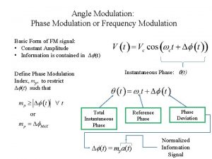
 Amplitude modulation vs frequency modulation
 Wave modulation
 Advantages of angle modulation
 Animals and human language شرح
 Communicative and informative signals
 Communicative signals and informative signals
 A collection of well-defined objects is called
 Software defined radio forum
 Software defined radio
 Diy sdr receiver
 Softrock sdr
 Hdsdr setup
 Awin radio
 Frameset trong html5
 Thứ tự các dấu thăng giáng ở hóa biểu
 101012 bằng
 Alleluia hat len nguoi oi
 Hươu thường đẻ mỗi lứa mấy con
 đại từ thay thế
 Vẽ hình chiếu vuông góc của vật thể sau
