Pulse Oximeter Measuring Oxygen Saturation Levels Final Presentation


- Slides: 20
Pulse Oximeter Measuring Oxygen Saturation Levels Final Presentation May 14, 2008 Tony Succar & Mustapha Okaddi
Table of Contents Objectives n Background n Progress n Results n Responsibilities n Timeline n Conclusion n
Objectives n To build a pulse oximeter – To achieve the Oxygen Saturation Level in blood by using two LED’s as transmitters and a Photodetector as the receiver. n An algorithm is developed through Lab. View
Background n The theory of measuring O 2 levels in blood began in the 1930’s. – Observe the skin tones n n Bluish skin color = Low Oxygen level = BAD The Modern Pulse Oximeter was invented in 1978 by Dr. William New at Stanford University. – It was a breakthrough that paved the way for medical advances in the years to come. – Huge impact on prevention of diseases & illnesses.
Engineering Approach Photodiode
Principle n By calculating the light absorption of the two wavelengths, the processor can compute the proportion of oxygenated hemoglobin.
Principle n Oxygen saturation level is a direct function of the following ratio:
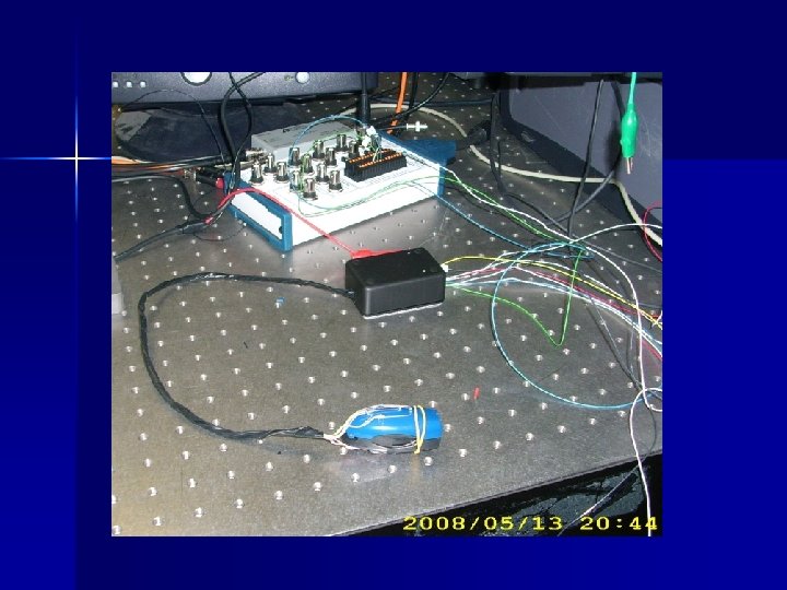
Stage 1: The beginning…
Stage 1 results n This setup was not effective – Numbers were inaccurate – Data was not stable – Sp. O 2 was very low, less than 50% n Solution – Stabilize the Photo Detector n Mount the Photo Detector and LED’s onto the table or onto the same plate.
Stage 2: Improvements Applied
Stage 2 results Ø New Plastic Fixture Numbers were greatly improved Ø Much more accurate Ø Much more stable Ø Ø However, problems persisted… Ø Although much more stable and closer to the expected value, still it was not stable enough: Ø 60% < Sp. O 2 < 95% Ambient light would creep in and effect the photosensor Ø The pressure on the finger was not stable Ø Ø This effects the accuracy of the data.
Stage 2 n Possible Solutions – Apply constant pressure to the finger – Block all external light sources from effecting the photosensor.
Stage 3: Final Design
Stage 3: Final Design
Lab. View Data from Final Design
Results and Data n Our final design was the best design. – Data is accurate – Numbers are relatively stable – Sp. O 2 is consistent n 90% < Sp. O 2 < 97% n New clip fixture n Overall, our project was a success! – Applied constant pressure to finger – Blocked all ambient light from effecting photosensor
Responsibilities n Both of us met at the lab many times the past several months to build and test the oximeter. n Both of us worked together on the Lab. View program and simulated it with the oximeter.
Time Line
Any Questions or Comments? ?