PCIe interface firmware and software Filippo Costa Sanjoy
- Slides: 19
PCIe interface firmware and software Filippo Costa Sanjoy Mukherjee Tuan Mate Nguyen ALICE CRU-O 2 CERN 1
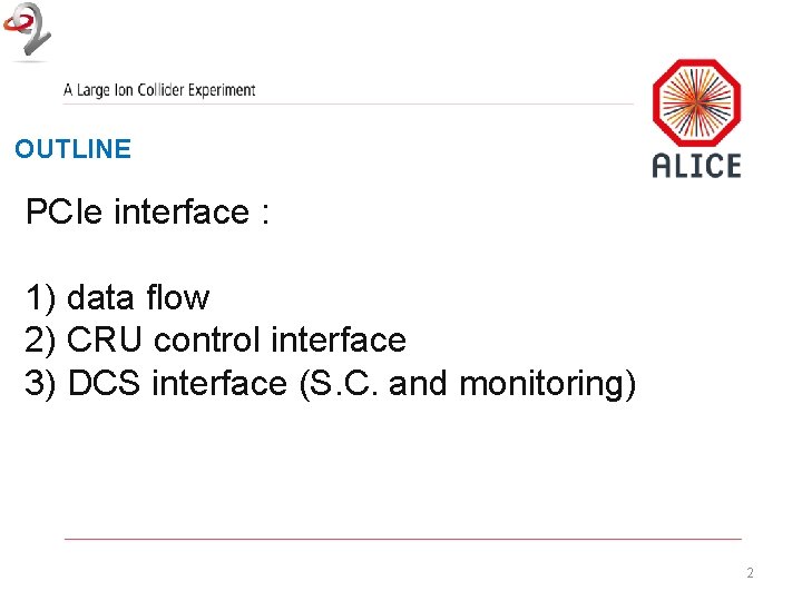
OUTLINE PCIe interface : 1) data flow 2) CRU control interface 3) DCS interface (S. C. and monitoring) 2
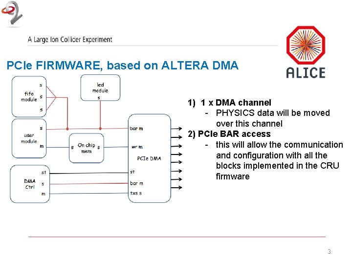
PCIe FIRMWARE, based on ALTERA DMA 1) 1 x DMA channel - PHYSICS data will be moved over this channel 2) PCIe BAR access - this will allow the communication and configuration with all the blocks implemented in the CRU firmware 3
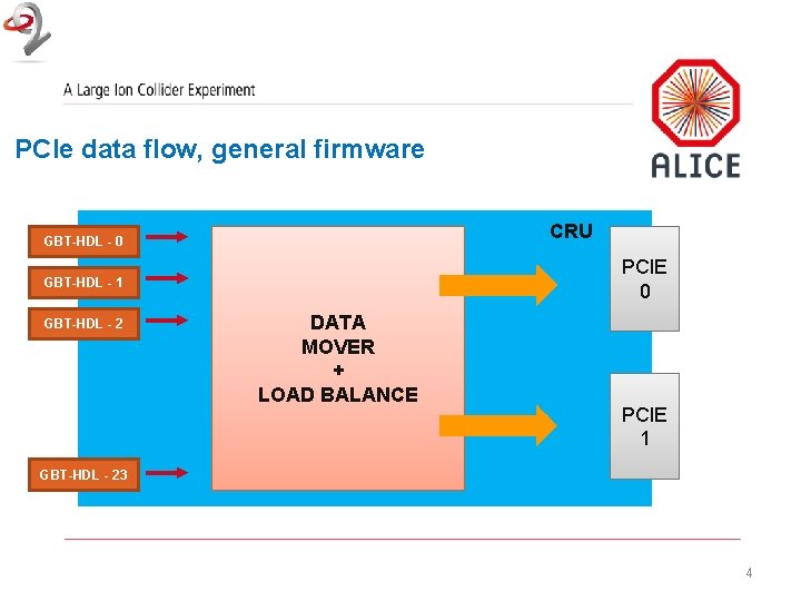
PCIe data flow, general firmware CRU GBT-HDL - 0 PCIE 0 GBT-HDL - 1 GBT-HDL - 2 DATA MOVER + LOAD BALANCE PCIE 1 GBT-HDL - 23 4
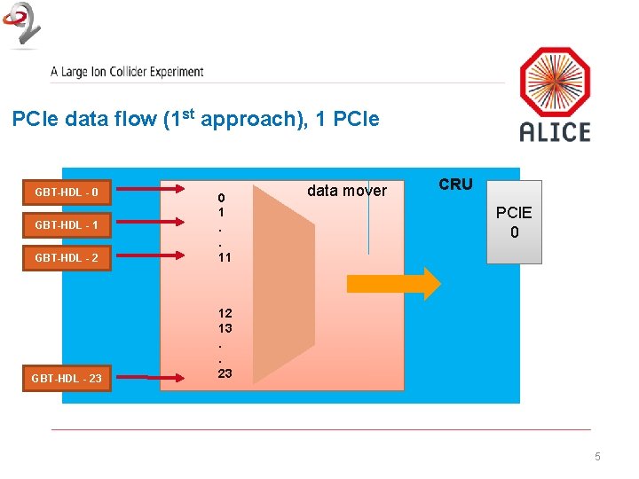
PCIe data flow (1 st approach), 1 PCIe GBT-HDL - 0 GBT-HDL - 2 0 1. . 11 GBT-HDL - 23 12 13. . 23 GBT-HDL - 1 data mover CRU PCIE 0 5
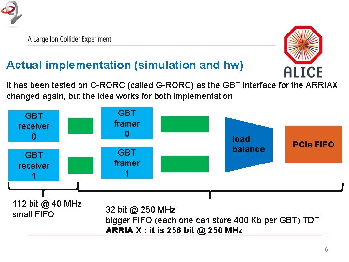
Actual implementation (simulation and hw) It has been tested on C-RORC (called G-RORC) as the GBT interface for the ARRIAX changed again, but the idea works for both implementation GBT receiver 0 GBT framer 0 GBT receiver 1 GBT framer 1 112 bit @ 40 MHz small FIFO load balance PCIe FIFO 32 bit @ 250 MHz bigger FIFO (each one can store 400 Kb per GBT) TDT ARRIA X : it is 256 bit @ 250 MHz 6
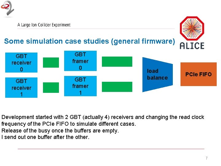
Some simulation case studies (general firmware) GBT receiver 0 GBT framer 0 GBT receiver 1 GBT framer 1 load balance PCIe FIFO Development started with 2 GBT (actually 4) receivers and changing the read clock frequency of the PCIe FIFO to simulate different cases. Release of the busy once the buffers are empty. I send out one buffer after the other. 7
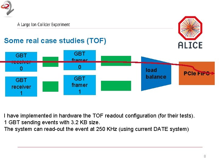
Some real case studies (TOF) GBT receiver 0 GBT framer 0 GBT receiver 1 GBT framer 1 load balance PCIe FIFO I have implemented in hardware the TOF readout configuration (for their tests). 1 GBT sending events with 3. 2 KB size. The system can read-out the event at 250 KHz (using current DATE system) 8
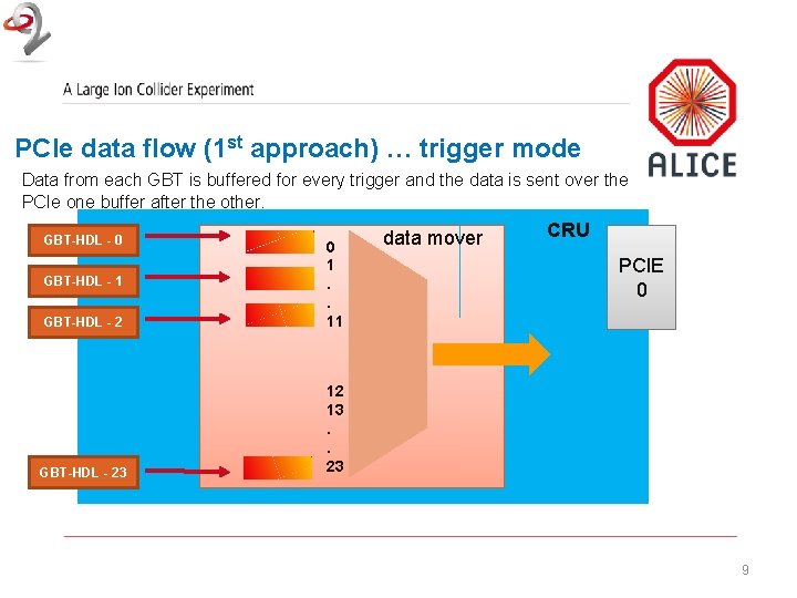
PCIe data flow (1 st approach) … trigger mode Data from each GBT is buffered for every trigger and the data is sent over the PCIe one buffer after the other. GBT-HDL - 0 GBT-HDL - 2 0 1. . 11 GBT-HDL - 23 12 13. . 23 GBT-HDL - 1 data mover CRU PCIE 0 9
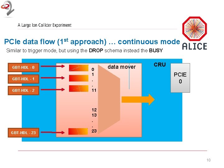
PCIe data flow (1 st approach) … continuous mode Similar to trigger mode, but using the DROP schema instead the BUSY GBT-HDL - 0 GBT-HDL - 2 0 1. . 11 GBT-HDL - 23 12 13. . 23 GBT-HDL - 1 data mover CRU PCIE 0 10
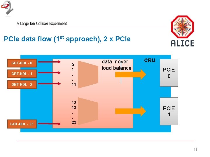
PCIe data flow (1 st approach), 2 x PCIe GBT-HDL - 0 GBT-HDL - 2 0 1. . 11 GBT-HDL - 23 12 13. . 23 GBT-HDL - 1 data mover load balance CRU PCIE 0 PCIE 1 11
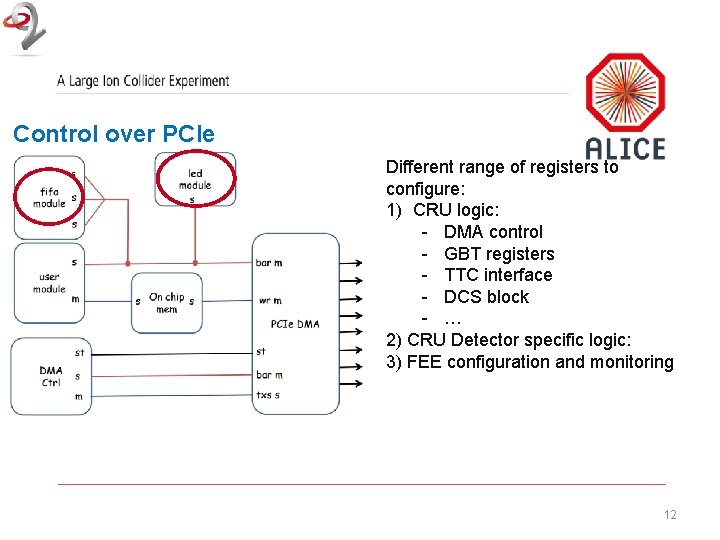
Control over PCIe Different range of registers to configure: 1) CRU logic: - DMA control - GBT registers - TTC interface - DCS block - … 2) CRU Detector specific logic: 3) FEE configuration and monitoring 12
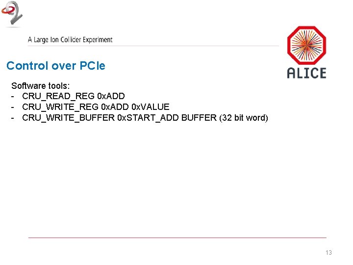
Control over PCIe Software tools: - CRU_READ_REG 0 x. ADD - CRU_WRITE_REG 0 x. ADD 0 x. VALUE - CRU_WRITE_BUFFER 0 x. START_ADD BUFFER (32 bit word) 13
Software interface PDA (Portable Driver Architecture) - PDA: a library for programming microdrivers - Move large parts of a device driver code to the user space without loss of speed - The device driver code is compatible with at least 28 kernel releases, easier to maintain http: //compeng. uni-frankfurt. de/fileadmin/Images/pda/eschweiler_lindenstruth_pda_rtlws. pdf 14
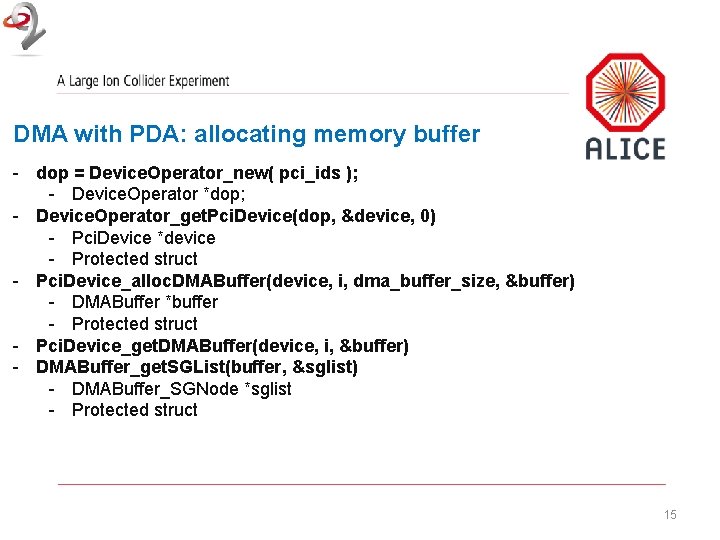
DMA with PDA: allocating memory buffer - dop = Device. Operator_new( pci_ids ); - Device. Operator *dop; - Device. Operator_get. Pci. Device(dop, &device, 0) - Pci. Device *device - Protected struct - Pci. Device_alloc. DMABuffer(device, i, dma_buffer_size, &buffer) - DMABuffer *buffer - Protected struct - Pci. Device_get. DMABuffer(device, i, &buffer) - DMABuffer_get. SGList(buffer, &sglist) - DMABuffer_SGNode *sglist - Protected struct 15
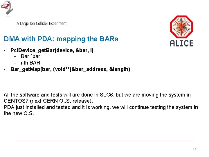
DMA with PDA: mapping the BARs - Pci. Device_get. Bar(device, &bar, i) - Bar *bar; - i-th BAR - Bar_get. Map(bar, (void**)&bar_address, &length) All the software and tests will are done in SLC 6, but we are moving the system in CENTOS 7 (next CERN O. . S. release). PDA just installed and tested and it is working, we will continue testing the system in the new O. S. 16
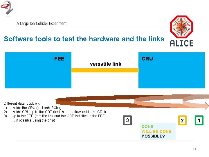
Software tools to test the hardware and the links FEE CRU versatile link Different data loopback: 1) Inside the CRU (test only PCIe), 2) Inside CRU up to the GBT (test the data flow inside the CRU) 3) Up to the FEE (test the link and the GBT installed in the FEE … if possible using the chip) 3 2 1 DONE WILL BE DONE POSSIBLE? 17
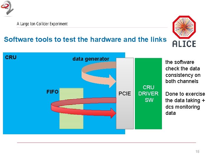
Software tools to test the hardware and the links CRU data generator FIFO the software check the data consistency on both channels PCIE CRU DRIVER SW Done to exercise the data taking + dcs monitoring data 18
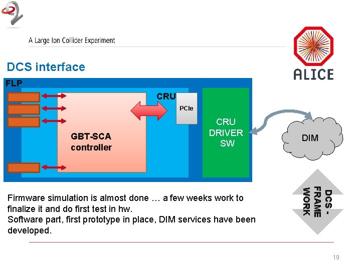
DCS interface FLP CRU PCIe GBT-SCA controller CRU DRIVER SW DCS FRAME WORK Firmware simulation is almost done … a few weeks work to finalize it and do first test in hw. Software part, first prototype in place, DIM services have been developed. DIM 19