Optical Smart Link EE 513 Communication Electronics Zheng
- Slides: 22
Optical Smart. Link EE 513 Communication Electronics Zheng Wang Xin Li Jialock Wong
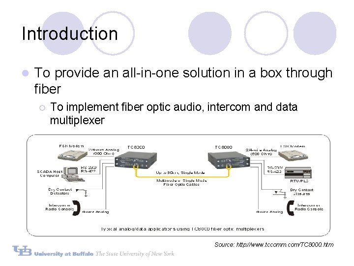
Introduction l To provide an all-in-one solution in a box through fiber ¡ To implement fiber optic audio, intercom and data multiplexer Source: http: //www. tccomm. com/TC 8000. htm
Goals l To study more about communication electronics such as fiber communication, DSP technology and multiplexing methods l To create a group oriented project l To create a fiber audio communication system with programmable DSP
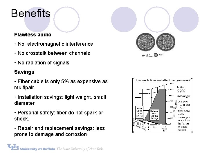
Benefits Flawless audio • No electromagnetic interference • No crosstalk between channels • No radiation of signals Savings • Fiber cable is only 5% as expensive as multipair • Installation savings: light weight, small diameter • Personal safety: fiber do not spark or shock, • Repair and replacement savings: less prone to damage and corrosion
Implementations l Integrate audio and data streaming over fiber optics cable in analog format l Support multiple channels l Implement FM multiplexing l Implement DSP programmable analysis such as spectrum analysis and signal conditioning at the receiver module
Procedures and timeline l Design and Simulate in Multisim (Workbench): 2/1 l Build analyze circuit: 2/15 l Code DSP program using TI C 6211: 3/15 l Test Overall circuit : 3/24 l Lab Demo: 4/7
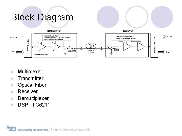
Block Diagram l l l Multiplexer Transmitter Optical Fiber Receiver Demultiplexer DSP TI C 6211
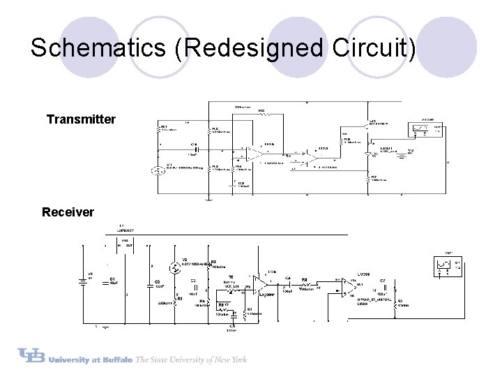
Schematics (Redesigned Circuit) Transmitter Receiver
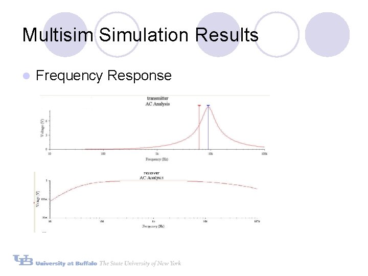
Multisim Simulation Results l Frequency Response
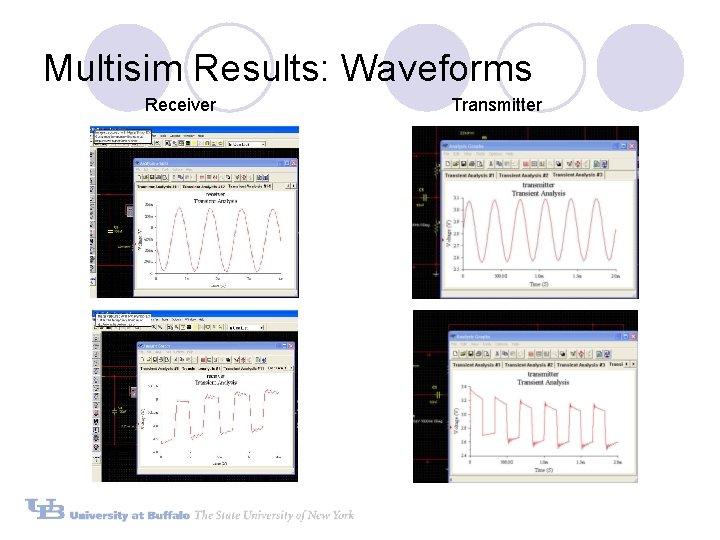
Multisim Results: Waveforms Receiver Transmitter
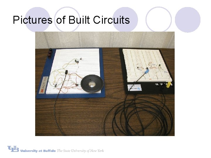
Pictures of Built Circuits
Laboratory Analysis v To analyze frequency response v To analyze supported inputs v To measure output performances v Instruments used: Agilent digital function generator, HP oscilloscope and Labview
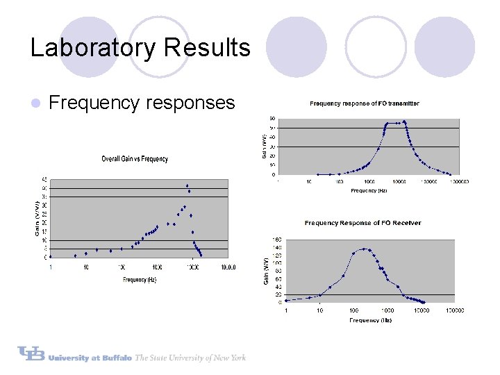
Laboratory Results l Frequency responses
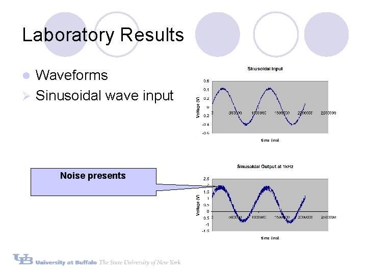
Laboratory Results Waveforms Ø Sinusoidal wave input l Noise presents
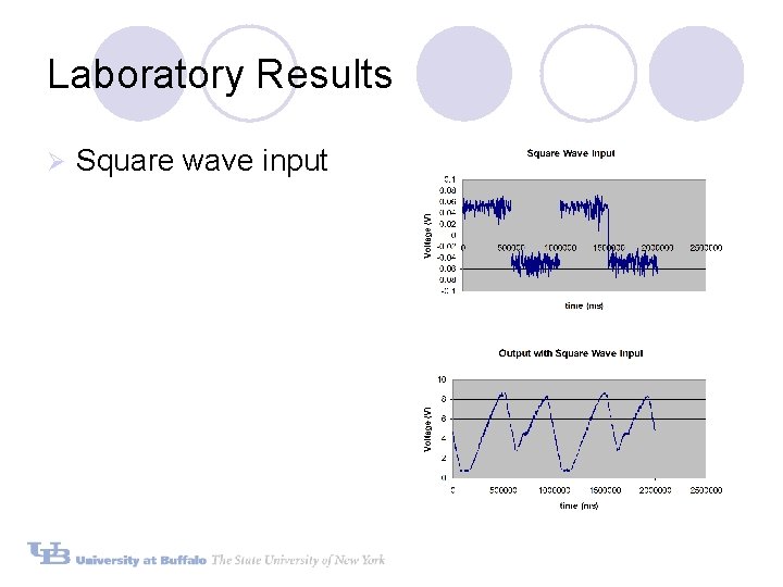
Laboratory Results Ø Square wave input
Laboratory Results Ø Real-time Music playback (DEMO) Original Music (Input) Recorded Music at Receiver (Output)
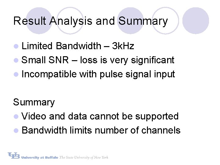
Result Analysis and Summary l Limited Bandwidth – 3 k. Hz l Small SNR – loss is very significant l Incompatible with pulse signal input Summary l Video and data cannot be supported l Bandwidth limits number of channels
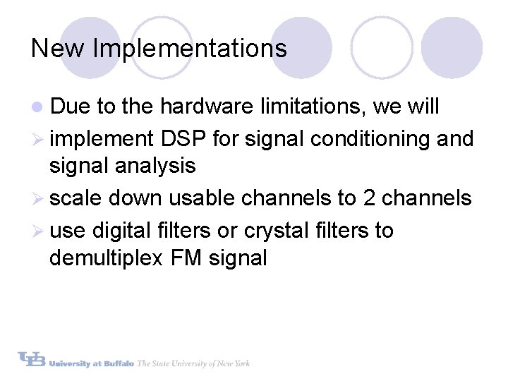
New Implementations l Due to the hardware limitations, we will Ø implement DSP for signal conditioning and signal analysis Ø scale down usable channels to 2 channels Ø use digital filters or crystal filters to demultiplex FM signal
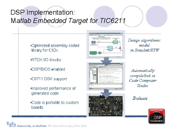
DSP Implementation: Matlab Embedded Target for TIC 6211
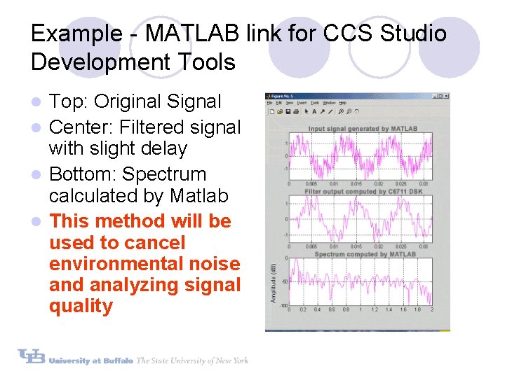
Example - MATLAB link for CCS Studio Development Tools Top: Original Signal l Center: Filtered signal with slight delay l Bottom: Spectrum calculated by Matlab l This method will be used to cancel environmental noise and analyzing signal quality l
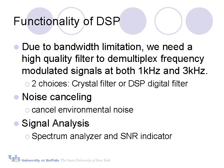
Functionality of DSP l Due to bandwidth limitation, we need a high quality filter to demultiplex frequency modulated signals at both 1 k. Hz and 3 k. Hz. ¡ 2 choices: Crystal filter or DSP digital filter l Noise canceling ¡ cancel l Signal environmental noise Analysis ¡ Spectrum analyzer and SNR indicator
Summary l Designed circuit has narrow bandwidth l We decided not to redesign the circuit, but to challenge ourselves by squeezing more information over limited bandwidth information