No 12 of 19 Geosynthetics in Erosion Protection



- Slides: 67
No. 12 of 19 Geosynthetics in Erosion Protection by Dr David Elton, P. E Auburn University The information presented in this document has been reviewed by the Education Committee of the International Geosynthetics Society and is believed to fairly represent the current state of practice. However, the International Geosynthetics Society does not accept any liability arising in any way from use of the information presented.
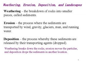
Geosynthetics in Sediment and Erosion Control • Introduction and Applications • What is it? • Erosion control is a means of keeping a soil in place or catching a soil after it has been displaced but before it moves into surface waters.
Why Is It Needed? There are public laws that : • preclude the polluting of surface waters with sediments • preserve topographic integrity • preserve soil for farming • preserve foundation integrity for structures founded on soil.
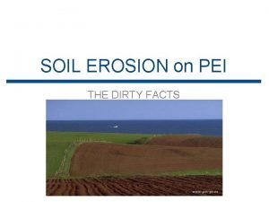
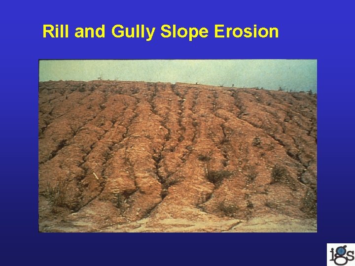
Rill and Gully Slope Erosion
Riverbank Erosion, Including Sapping (Formation of Caves)
Where Is It Needed? • It is needed on construction and agricultural sites and natural places where water causes soils to displace. • In short: where soil and moving water interact at the ground surface
Factors Influencing Types of Erosion • Rainfall-induced erosion factors: – – – intensity and duration of rainfall slope of land soil type • All affect the amount of erosion and the erosion control measures selected.
Factors Influencing Types Of Erosion (Continued) • Shoreline erosion factors: – soil type – wave height – beach slope – duration and intensity of storm • All affect the amount of erosion.
Factors Influencing Types Of Erosion (Continued) • Scour: – The amount of scour, around bridge piers for example, is affected by pier shape, depth of stream, storm duration and channel shape, in addition to soil type.
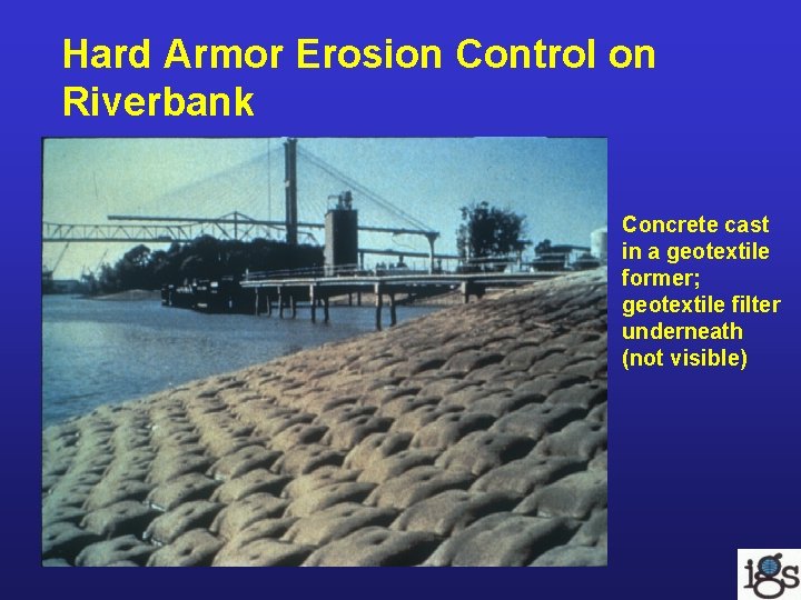
Hard Armor Erosion Control on Riverbank Concrete cast in a geotextile former; geotextile filter underneath (not visible)
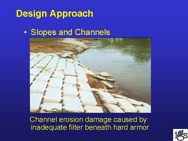
Design Approach • Slopes and Channels Channel erosion damage caused by inadequate filter beneath hard armor
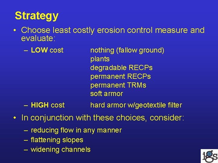
Strategy • Choose least costly erosion control measure and evaluate: – LOW cost nothing (fallow ground) plants degradable RECPs permanent TRMs soft armor – HIGH cost hard armor w/geotextile filter • In conjunction with these choices, consider: – reducing flow in any manner – flattening slopes – widening channels
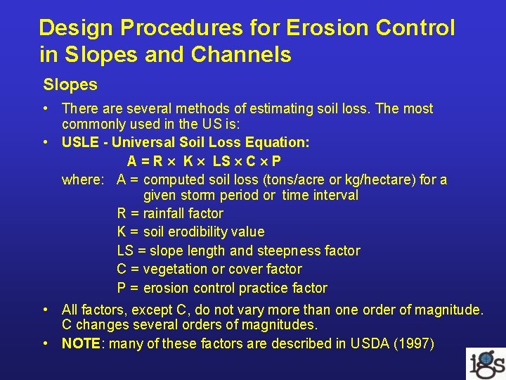
Design Procedures for Erosion Control in Slopes and Channels Slopes • There are several methods of estimating soil loss. The most commonly used in the US is: • USLE - Universal Soil Loss Equation: A = R K LS C P where: A = computed soil loss (tons/acre or kg/hectare) for a given storm period or time interval R = rainfall factor K = soil erodibility value LS = slope length and steepness factor C = vegetation or cover factor P = erosion control practice factor • All factors, except C, do not vary more than one order of magnitude. C changes several orders of magnitudes. • NOTE: many of these factors are described in USDA (1997)
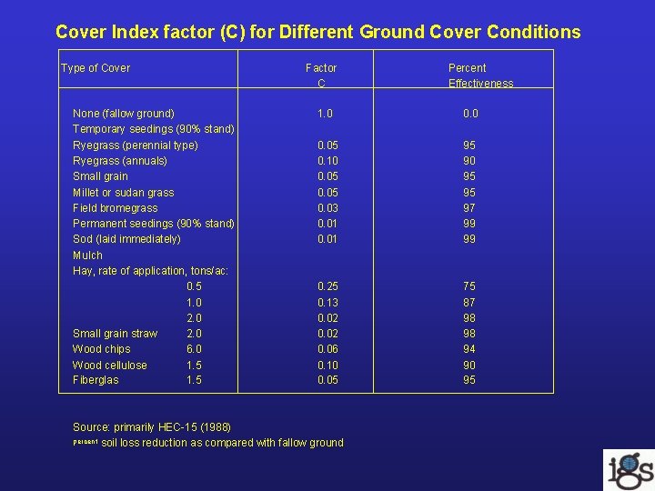
Cover Index factor (C) for Different Ground Cover Conditions Type of Cover None (fallow ground) Temporary seedings (90% stand) Ryegrass (perennial type) Ryegrass (annuals) Small grain Millet or sudan grass Field bromegrass Permanent seedings (90% stand) Sod (laid immediately) Mulch Hay, rate of application, tons/ac: 0. 5 1. 0 2. 0 Small grain straw 2. 0 Wood chips 6. 0 Wood cellulose 1. 5 Fiberglas 1. 5 Factor C 1. 0 0. 05 0. 10 0. 05 0. 03 0. 01 95 90 95 95 97 99 99 0. 25 0. 13 0. 02 0. 06 0. 10 0. 05 75 87 98 98 94 90 95 Source: primarily HEC-15 (1988) soil loss reduction as compared with fallow ground percent Percent Effectiveness
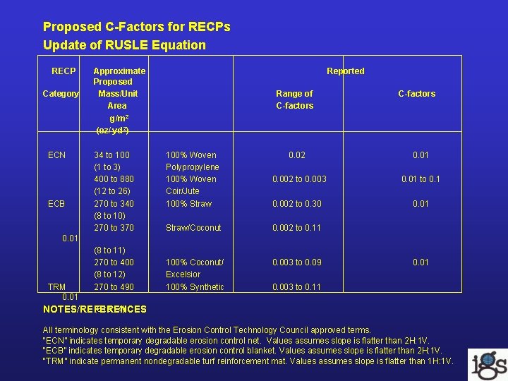
Proposed C-Factors for RECPs Update of RUSLE Equation RECP Category ECN ECB Approximate Proposed Mass/Unit Area g/m 2 (oz/ yd 2) 34 to 100 (1 to 3) 400 to 880 (12 to 26) 270 to 340 (8 to 10) 270 to 370 Reported Range of C-factors 100% Woven Polypropylene 100% Woven Coir/Jute 100% Straw 0. 02 0. 01 0. 002 to 0. 003 0. 01 to 0. 1 0. 002 to 0. 30 0. 01 Straw/Coconut 0. 002 to 0. 11 100% Coconut/ Excelsior 100% Synthetic 0. 003 to 0. 09 0. 01 TRM 0. 01 (8 to 11) 270 to 400 (8 to 12) 270 to 490 0. 01 0. 003 to 0. 11 (8 to 14) NOTES/REFERENCES All terminology consistent with the Erosion Control Technology Council approved terms. “ECN” indicates temporary degradable erosion control net. Values assumes slope is flatter than 2 H: 1 V. “ECB” indicates temporary degradable erosion control blanket. Values assumes slope is flatter than 2 H: 1 V. “TRM” indicate permanent nondegradable turf reinforcement mat. Values assumes slope is flatter than 1 H: 1 V.
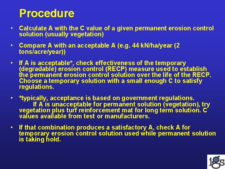
Procedure • Calculate A with the C value of a given permanent erosion control solution (usually vegetation) • Compare A with an acceptable A (e. g. 44 k. N/ha/year (2 tons/acre/year)) • If A is acceptable*, check effectiveness of the temporary (degradable) erosion control (RECP) measure used to establish the permanent erosion control solution over the life of the RECP. Choose a temporary solution with a small enough C to satisfy regulations. • *typically, acceptance is based on government regulations. If A is unacceptable for permanent solution (vegetation), try vegetation plus turf reinforcement mat for long term solution. C values available from test or manufacturers. • If that combination produces a satisfactory A, check A for temporary erosion control solution used while permanent solution is taking hold.
Channel Linings • Two Common Methods of Analysis: – Permissible velocity in channel – Permissible shear stress in channel
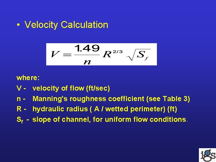
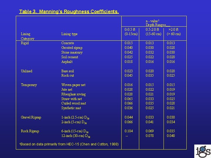
• Velocity Calculation where: V - velocity of flow (ft/sec) n - Manning's roughness coefficient (see Table 3) R - hydraulic radius ( A / wetted perimeter) (ft) Sf - slope of channel, for uniform flow conditions.
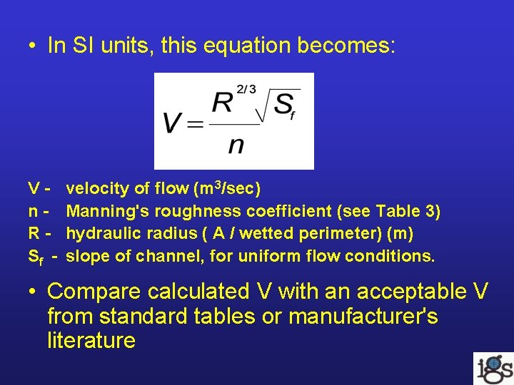
• In SI units, this equation becomes: Vn. RSf - velocity of flow (m 3/sec) Manning's roughness coefficient (see Table 3) hydraulic radius ( A / wetted perimeter) (m) slope of channel, for uniform flow conditions. • Compare calculated V with an acceptable V from standard tables or manufacturer's literature
Table 3. Manning’s Roughness Coefficients. n - value 1 Depth Ranges 0. 5 -2. 0 ft >2. 0 ft (15 -60 cm) (> 60 cm) Lining Category Rigid Lining type 0 -0. 5 ft (0 -15 cm) Concrete Grouted riprap Stone masonry Soil cement Asphalt 0. 015 0. 040 0. 042 0. 025 0. 018 0. 013 0. 030 0. 032 0. 022 0. 016 0. 013 0. 028 0. 030 0. 020 0. 016 Unlined Bare soil Rock cut 0. 023 0. 045 0. 020 0. 035 0. 020 0. 025 Temporary Woven paper net Jute net Fiberglass roving Straw with net Curled wood mat Synthetic mat 0. 016 0. 028 0. 065 0. 066 0. 036 0. 015 0. 022 0. 021 0. 033 0. 035 0. 025 0. 019 0. 025 0. 028 0. 021 Gravel Riprap 1 -inch (2. 5 -cm) D 50 2 -inch (5 -cm) D 50 0. 044 0. 066 0. 033 0. 041 0. 030 0. 034 Rock Riprap 6 -inch (15 -cm) D 50 12 -inch (30 -cm) D 50 0. 104 -- 0. 069 0. 078 0. 035 0. 040 1 Based on data primarily from HEC-15 (Chen and Cotton, 1988)
Notes: • Values listed are representative values for the respective depth ranges. • Manning’s roughness coefficients, n, vary with the flow depth. • n-values for vegetative linings are found in Chen and Cotton (1988) (HEC-15) on pages 42 - 46. • Another method is to evaluate the shear stress on the ground surface caused by the running water. (Method follows).
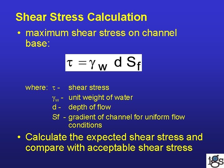
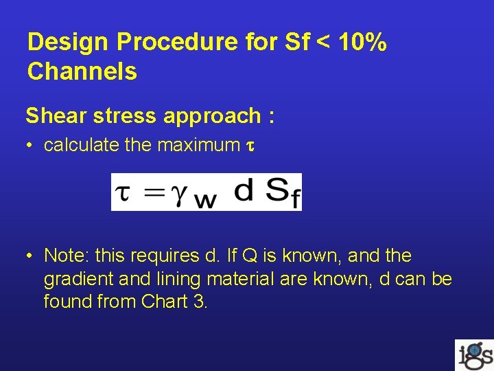
Shear Stress Calculation • maximum shear stress on channel base: where: w d. Sf - shear stress unit weight of water depth of flow gradient of channel for uniform flow conditions • Calculate the expected shear stress and compare with acceptable shear stress
Design Variables • increasing the width/depth ratio of channel reduces – channel slope: flatter reduces (note: 10% is considered a "steep Channel". Sf > 10% usually requires hard armor)
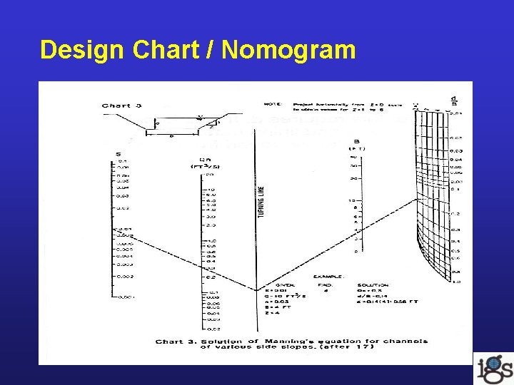
Design Procedure for Sf < 10% Channels Shear stress approach : • calculate the maximum • Note: this requires d. If Q is known, and the gradient and lining material are known, d can be found from Chart 3.
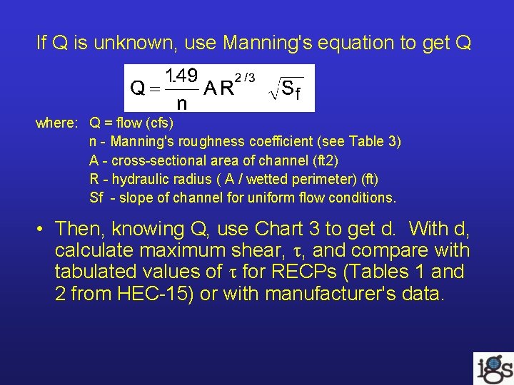
If Q is unknown, use Manning's equation to get Q where: Q = flow (cfs) n - Manning's roughness coefficient (see Table 3) A - cross-sectional area of channel (ft 2) R - hydraulic radius ( A / wetted perimeter) (ft) Sf - slope of channel for uniform flow conditions. • Then, knowing Q, use Chart 3 to get d. With d, calculate maximum shear, , and compare with tabulated values of for RECPs (Tables 1 and 2 from HEC-15) or with manufacturer's data.
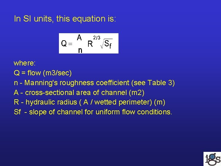
In SI units, this equation is: where: Q = flow (m 3/sec) n - Manning's roughness coefficient (see Table 3) A - cross-sectional area of channel (m 2) R - hydraulic radius ( A / wetted perimeter) (m) Sf - slope of channel for uniform flow conditions.
Design Chart / Nomogram
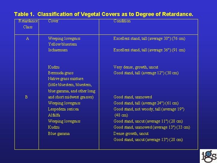
Table 1. Classification of Vegetal Covers as to Degree of Retardance Class A B Cover Condition Weeping lovegrass Yellow bluestem Ischaemum Excellent stand, tall (average 30") (76 cm) Kudzu Bermuda grass Native grass mixture. (little bluestem, blue gamma, and other long and short midwest grasses) Weeping lovegrass Lespedeza sericea Alfalfa Weeping lovegrass Kudzu Blue gamma Very dense, growth, uncut Good stand, tall (average 12") (30 cm) Excellent stand, tall (average 36") (91 cm) Good stand, unmowed Good stand, tall (average 24") (61 cm) Good stand, not woody, tall (average 19") (48 cm) Good stand, uncut (average 11") (28 cm) Good stand, unmowed (average 13") (33 cm) Dense growth, uncut Good stand, uncut (average 13") (28 cm)
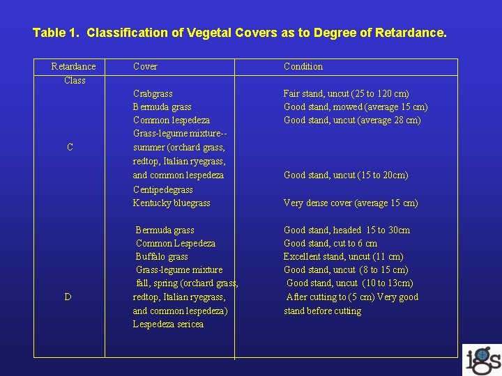
Table 1. Classification of Vegetal Covers as to Degree of Retardance Class C D Cover Condition Crabgrass Bermuda grass Common lespedeza Grass-legume mixture-summer (orchard grass, redtop, Italian ryegrass, and common lespedeza Centipedegrass Kentucky bluegrass Fair stand, uncut (25 to 120 cm) Good stand, mowed (average 15 cm) Good stand, uncut (average 28 cm) Bermuda grass Common Lespedeza Buffalo grass Grass-legume mixture fall, spring (orchard grass, redtop, Italian ryegrass, and common lespedeza) Lespedeza sericea Good stand, headed 15 to 30 cm Good stand, cut to 6 cm Excellent stand, uncut (11 cm) Good stand, uncut (8 to 15 cm) Good stand, uncut (10 to 13 cm) After cutting to (5 cm) Very good stand before cutting Good stand, uncut (15 to 20 cm) Very dense cover (average 15 cm)
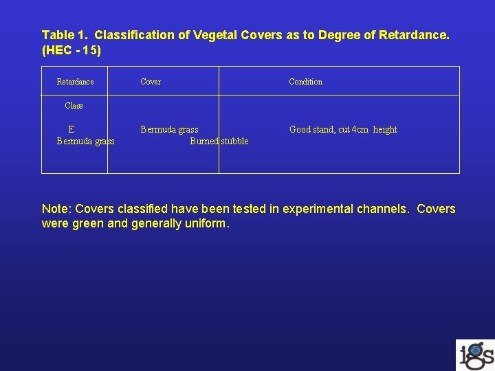
Table 1. Classification of Vegetal Covers as to Degree of Retardance. (HEC - 15) Retardance Cover Condition Bermuda grass Burned stubble Good stand, cut 4 cm height Class E Bermuda grass Note: Covers classified have been tested in experimental channels. Covers were green and generally uniform.
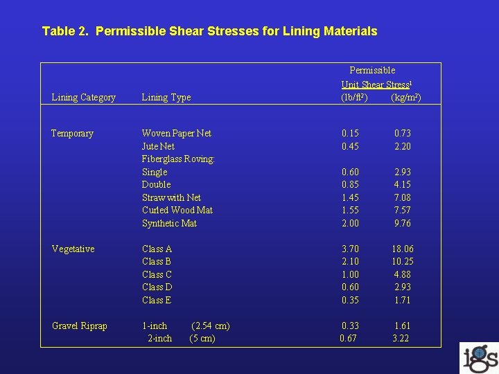
Table 2. Permissible Shear Stresses for Lining Materials Permissible Unit Shear Stress 1 (lb/ft 2) (kg/m 2) Lining Category Lining Type Temporary Woven Paper Net Jute Net Fiberglass Roving: Single Double Straw with Net Curled Wood Mat Synthetic Mat 0. 15 0. 45 0. 73 2. 20 0. 60 0. 85 1. 45 1. 55 2. 00 2. 93 4. 15 7. 08 7. 57 9. 76 Vegetative Class A Class B Class C Class D Class E 3. 70 2. 10 1. 00 0. 60 0. 35 18. 06 10. 25 4. 88 2. 93 1. 71 Gravel Riprap 1 -inch 2 -inch 0. 33 0. 67 1. 61 3. 22 (2. 54 cm) (5 cm)
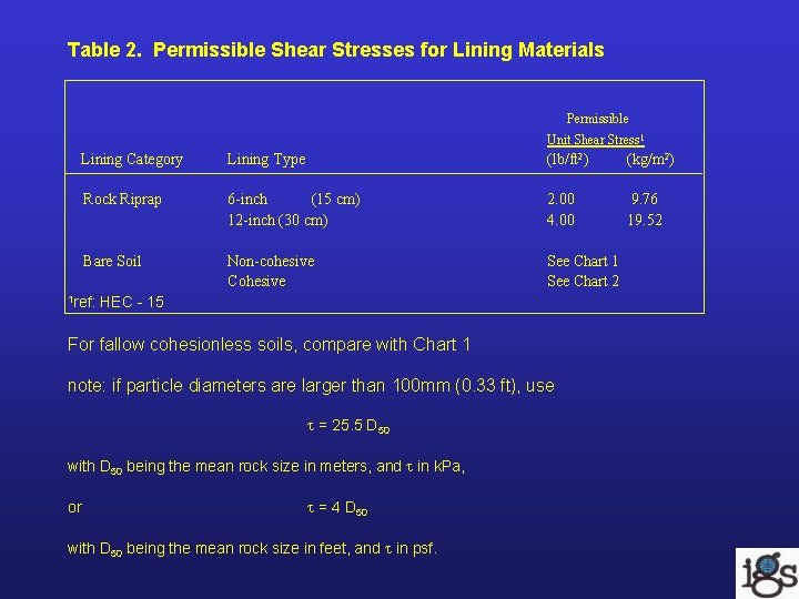
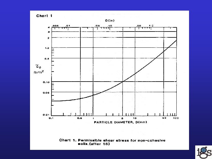
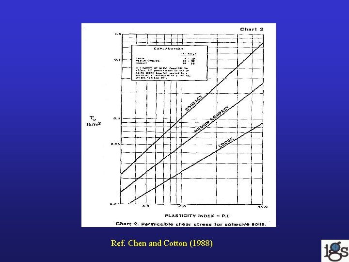
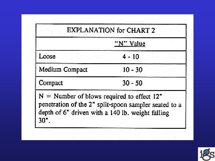
Table 2. Permissible Shear Stresses for Lining Materials Permissible Unit Shear Stress 1 Lining Category Lining Type (lb/ft 2) (kg/m 2) Rock Riprap 6 -inch (15 cm) 12 -inch (30 cm) 2. 00 4. 00 9. 76 19. 52 Bare Soil Non-cohesive Cohesive See Chart 1 See Chart 2 1 ref: HEC - 15 For fallow cohesionless soils, compare with Chart 1 note: if particle diameters are larger than 100 mm (0. 33 ft), use = 25. 5 D 50 with D 50 being the mean rock size in meters, and in k. Pa, or = 4 D 50 with D 50 being the mean rock size in feet, and in psf.
Ref. Chen and Cotton (1988)
Erosion Control Using Geosynthetics Applications: • Introduction • Useful in scour, surface and shoreline protection • Geosynthetic functions include: – filtration – containment (bags) – protection – providing a medium for plant growth
Erosion Control Using Geosynthetics Scour Applications – Bridge pier footing – Canal Lining
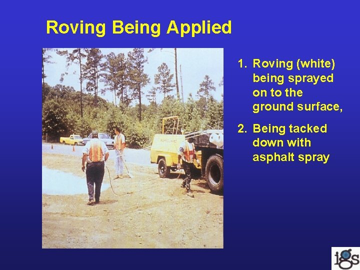
Surface Protection Philosophy • reduce the intensity of the raindrops impacting the soil, reduce the speed of runoff, increase the amount of water that soaks into the soil rather than running off. Roving • Roving is fine threads spread out on the ground surface, tacked down with a spray that holds it in place while vegetation takes hold. • Roving is applied manually, with a light machine. The method is slow, but useful in smaller areas with uneven surfaces.
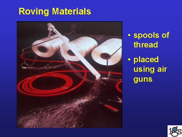
Roving Materials • spools of thread • placed using air guns
Roving Being Applied 1. Roving (white) being sprayed on to the ground surface, 2. Being tacked down with asphalt spray
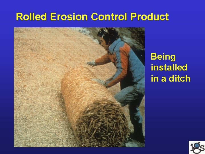
Rolled Erosion Control Product Being installed in a ditch
Permanent Installations (Permanent Erosion and Revegetation Mats) Soft PERMs • Turf Reinforcement Mats (TRMs) – TRMs are typically placed on the surface and then filled in with soil. They reinforce the ground surface, making erosion more difficult. The TERM holds the soil in place while vegetation takes hold. • Erosion Control and Revegetation Mats (ECRMs) – These combine surface control and surface slope stabilization at the same time.
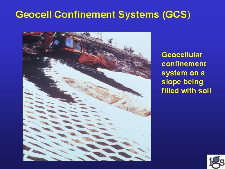
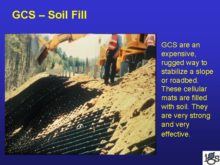
Geocell Confinement Systems (GCS) Geocellular confinement system on a slope being filled with soil
GCS – Soil Fill GCS are an expensive, rugged way to stabilize a slope or roadbed. These cellular mats are filled with soil. They are very strong and very effective.
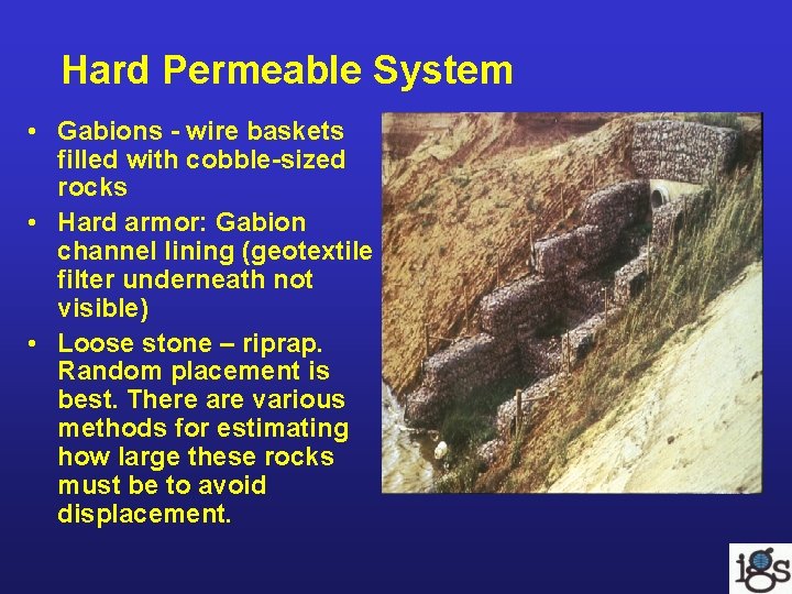
Hard Permeable System • Gabions - wire baskets filled with cobble-sized rocks • Hard armor: Gabion channel lining (geotextile filter underneath not visible) • Loose stone – riprap. Random placement is best. There are various methods for estimating how large these rocks must be to avoid displacement.
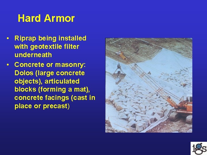
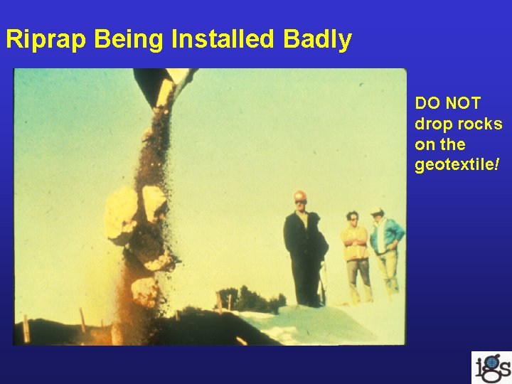
Hard Armor • Riprap being installed with geotextile filter underneath • Concrete or masonry: Dolos (large concrete objects), articulated blocks (forming a mat), concrete facings (cast in place or precast)
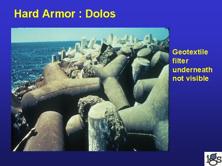
Hard Armor : Dolos Geotextile filter underneath not visible
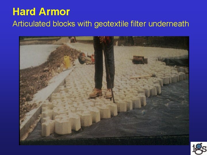
Hard Armor Articulated blocks with geotextile filter underneath
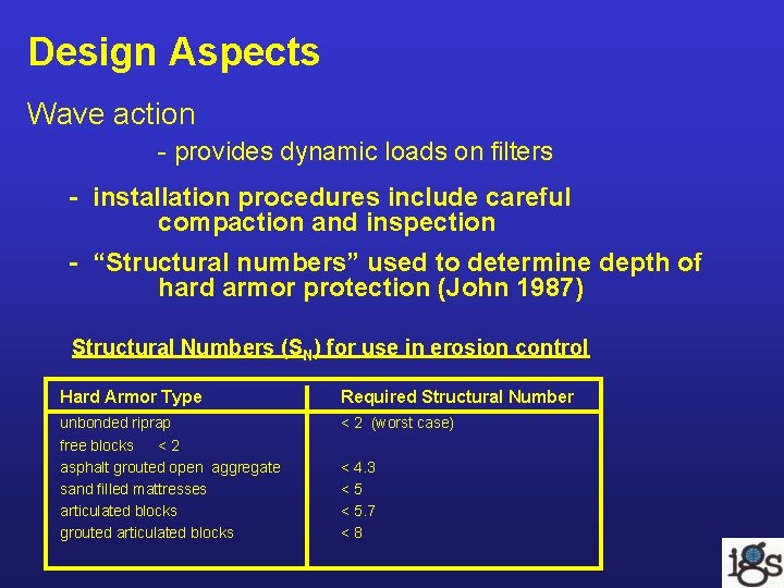
Design Aspects Wave action - provides dynamic loads on filters - installation procedures include careful compaction and inspection - “Structural numbers” used to determine depth of hard armor protection (John 1987) Structural Numbers (SN) for use in erosion control Hard Armor Type Required Structural Number unbonded riprap free blocks <2 asphalt grouted open aggregate sand filled mattresses articulated blocks grouted articulated blocks < 2 (worst case) < 4. 3 <5 < 5. 7 <8
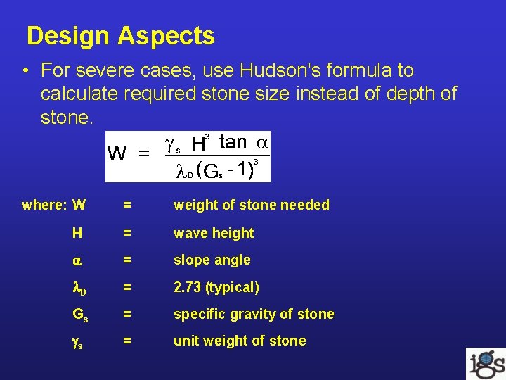
Design Aspects • For severe cases, use Hudson's formula to calculate required stone size instead of depth of stone. where: W = weight of stone needed H = wave height = slope angle D = 2. 73 (typical) Gs = specific gravity of stone s = unit weight of stone
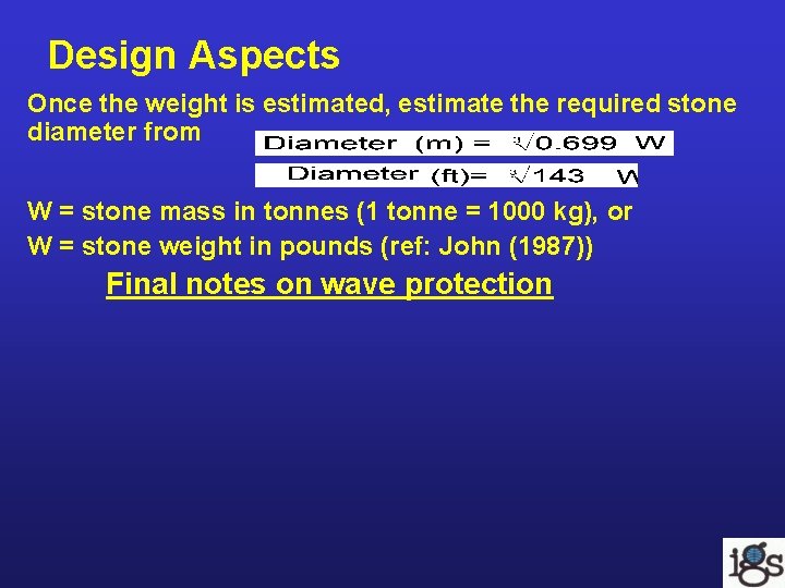
Design Aspects Once the weight is estimated, estimate the required stone diameter from W = stone mass in tonnes (1 tonne = 1000 kg), or W = stone weight in pounds (ref: John (1987)) Final notes on wave protection
Riprap Being Installed Badly DO NOT drop rocks on the geotextile!
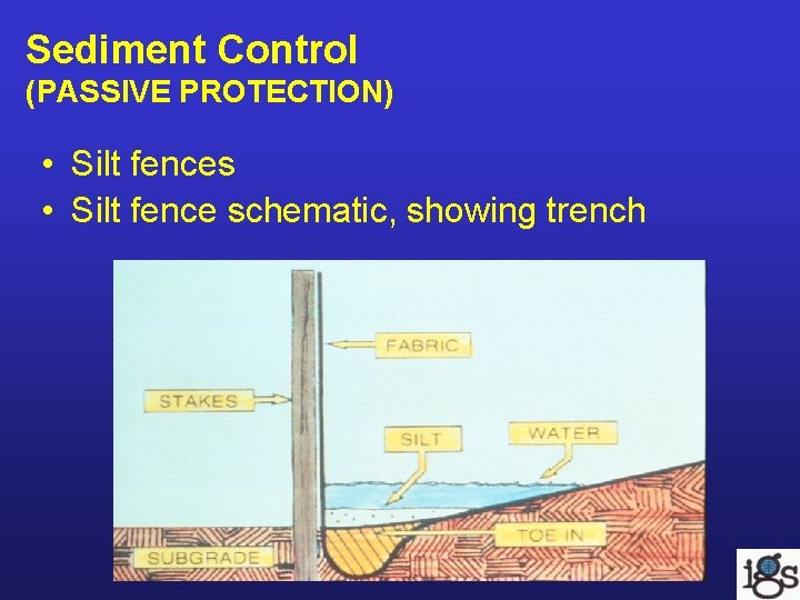
Sediment Control (PASSIVE PROTECTION) • Silt fences • Silt fence schematic, showing trench
Silt Fences • Purpose – To prevent soil from getting into surface waters. • Functioning – The silt fence forms a small stilling basin detention (pond) for the sediment. • Criteria – ultraviolet light (UV) protection – tensile strength of geotextile – filtration - prevention of migration of most soil particles through the geotextile into a drainage medium. • Installation – Cut a trench for the geotextile and compact it with soil into the trench. Drive stakes adequately deep to provide the lateral resistance.
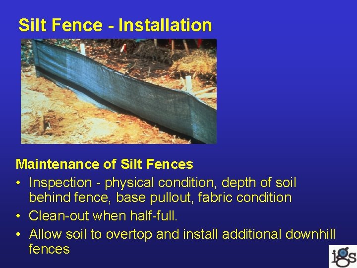
Silt Fence - Installation Maintenance of Silt Fences • Inspection - physical condition, depth of soil behind fence, base pullout, fabric condition • Clean-out when half-full. • Allow soil to overtop and install additional downhill fences
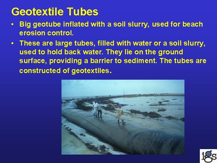
Geotextile Tubes • Big geotube inflated with a soil slurry, used for beach erosion control. • These are large tubes, filled with water or a soil slurry, used to hold back water. They lie on the ground surface, providing a barrier to sediment. The tubes are constructed of geotextiles.
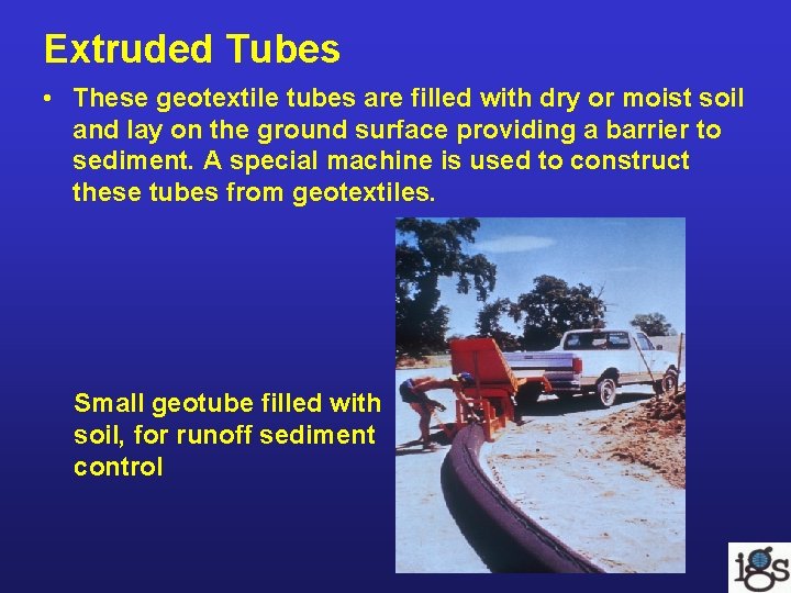
Extruded Tubes • These geotextile tubes are filled with dry or moist soil and lay on the ground surface providing a barrier to sediment. A special machine is used to construct these tubes from geotextiles. Small geotube filled with soil, for runoff sediment control
Construction Considerations Erosion control blankets • cover before use to avoid moisture, degradation and/or sprouting, and dust accumulation • Installation: - place in direction of resistance to uplift from wind/water - stake blankets to ground to resist wind and plant uplift and to keep blanket from sliding downslope - follow manufacturer’s directions
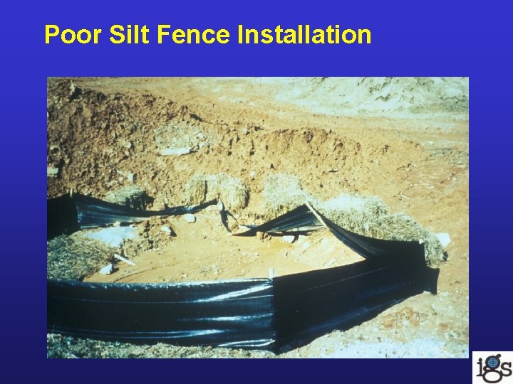
Construction Considerations • Silt fences – trenching in very important so soil doesn’t travel under fence – geotextile faces uphill (stake is on downhill side of geotextile) be sure the fence has adequate height when crossing swale to avoid loss of soil around edges of fence
Poor Silt Fence Installation
Vegetation • General: – vegetation needs light, water – must have climate compatibility – must have biological compatibility • Sources of information on vegetation: – Gray, D. H. , Leiser, A. T. (1982) Biotechnical Slope Protection and Erosion Control, Van Nostrand Reinhold, NY. – USDA Soil Conservation Service (1992) Field Handbook, Chapter 18 "Soil – Bioengineering for Upland Slope Protection and Erosion Reduction", U. S. Gov. Printing Office, Washington, D. C.
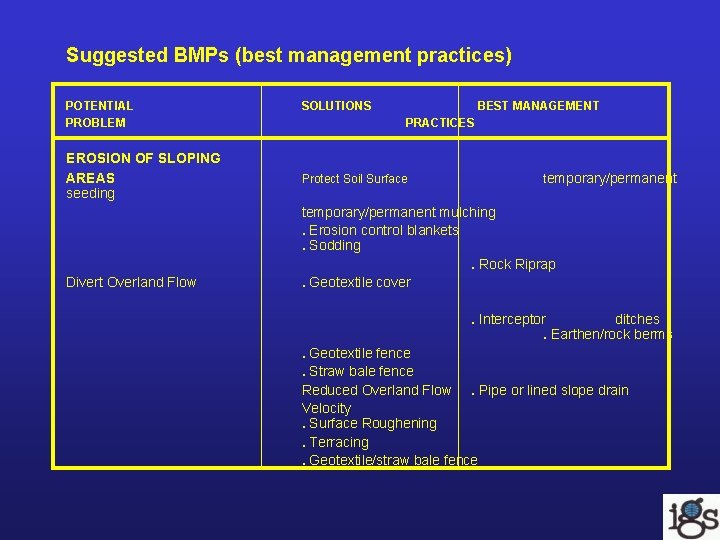
Suggested BMPs (best management practices) POTENTIAL PROBLEM EROSION OF SLOPING AREAS seeding Divert Overland Flow SOLUTIONS BEST MANAGEMENT PRACTICES Protect Soil Surface temporary/permanent mulching. Erosion control blankets. Sodding. Rock Riprap. Geotextile cover. Interceptor ditches. Earthen/rock berms. Geotextile fence. Straw bale fence Reduced Overland Flow. Pipe or lined slope drain Velocity. Surface Roughening. Terracing. Geotextile/straw bale fence
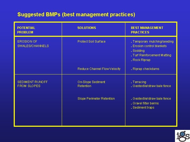
Suggested BMPs (best management practices) POTENTIAL PROBLEM SOLUTIONS BEST MANAGEMENT PRACTICES EROSION OF SWALES/CHANNELS Protect Soil Surface . Temporary mulching/seeding. Erosion control blankets. Sodding. Turf Reinforcement Matting. Rock Riprap Reduce Channel Flow Velocity . Riprap checkdams On-Slope Sediment Retention . Terracing. Geotextile/straw bale fence Slope Perimeter Retention . Geotextile/straw bale fence. Gravel filter berms. Sediment traps SEDIMENT RUNOFF FROM SLOPES
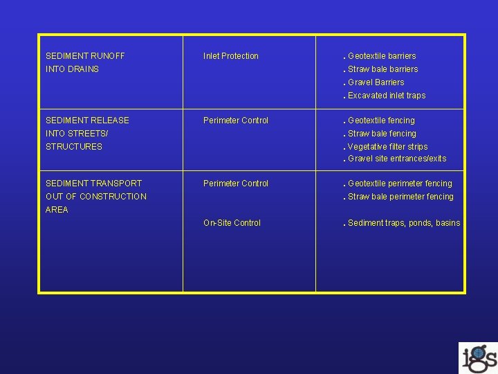
SEDIMENT RUNOFF Inlet Protection INTO DRAINS . Geotextile barriers. Straw bale barriers. Gravel Barriers. Excavated inlet traps SEDIMENT RELEASE Perimeter Control . Geotextile fencing INTO STREETS/ . Straw bale fencing STRUCTURES . Vegetative filter strips. Gravel site entrances/exits SEDIMENT TRANSPORT Perimeter Control OUT OF CONSTRUCTION . Geotextile perimeter fencing. Straw bale perimeter fencing AREA On-Site Control . Sediment traps, ponds, basins
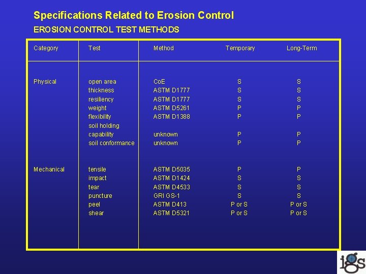
Specifications Related to Erosion Control EROSION CONTROL TEST METHODS Category Test Method Physical open area thickness resiliency weight flexibility soil holding capability soil conformance Co. E ASTM D 1777 ASTM D 5261 ASTM D 1388 S S S P P unknown P P tensile impact tear puncture peel shear ASTM D 5035 ASTM D 1424 ASTM D 4533 GRI GS-1 ASTM D 413 ASTM D 5321 P S S S P or S Mechanical Temporary Long-Term
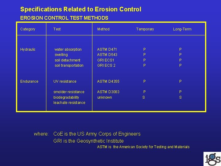
Specifications Related to Erosion Control EROSION CONTROL TEST METHODS Category Test Method Temporary Long-Term Hydraulic water absorption swelling soil detachment soil transportation ASTM D 471 ASTM D 543 GRI ECS 1 GRI ECS 2 P P P P Endurance UV resistance ASTM D 4355 P P smolder resistance biodegradability leachate resistance ASTM D 3083 unknown P S where: Co. E is the US Army Corps of Engineers GRI is the Geosynthetic Institute ASTM is the American Society for Testing and Materials
References/Bibliography International Erosion Control Association P. O. Box 4904 Steamboat Springs, CO 80477 USA http: //www. ectc. org/ phone: 1 (303) 879 -3010 Chen, Y. H. and G. K. Cotton (1988) Design of Roadside Channels with Flexible Linings, US Federal Highway Administration report HEC-15/FHWA-1 P-87 -7, Mc. Lean, VA, USA. Gray, D. H. (1996) Biotechnical and soil bioengineering slope stabilization: a practical guide for erosion control, New York : John Wiley & Sons, 378 p. : ill. ; 25 cm. Gray, D. H. , Leiser, A. T. (1982) Biotechnical Slope Protection and Erosion Control, Van Nostrand Reinhold, NY. HEC-15 (1988) Chen, Y. H. and G. K. Cotton, Design of Roadside Channels with Flexible Linings, US Federal Highway Administration report /FHWA-1 P-87 -7, Mc. Lean, VA, USA. John, N. W. M. (1987) Geotextiles, Chapman and Hall, NY. Temple, D. M. , Robinson, K. M, Ahring, R. M. , David, A. G. , (1987) Stability Design of Grass-lined Open Channels, USDA, Agricultural Handbook 667, 175 pp. USDA (1997) Predicting Soil Erosion by Water: A Guide to Conservation Planning With the Revised Universal Soil Loss Equation (RUSLE), Agricultural Handbook No. 703. USDA Soil Conservation Service (1992) Field Handbook, Chapter 18 "Soil Bioengineering for Upland Slope Protection and Erosion Reduction", U. S. Gov. Printing Office, Washington, D. C.