Motor applications Motor applications Cut out view of


- Slides: 41
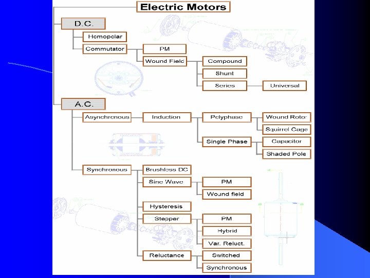
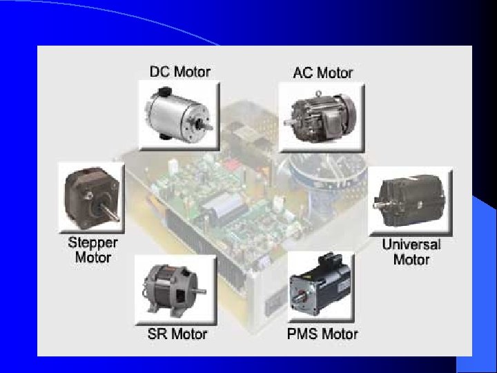
Motor applications
Motor applications
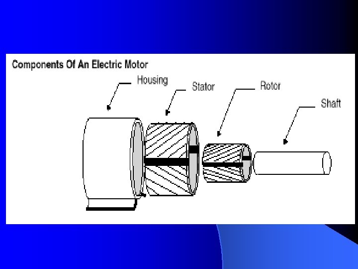
Cut out view of Induction motor
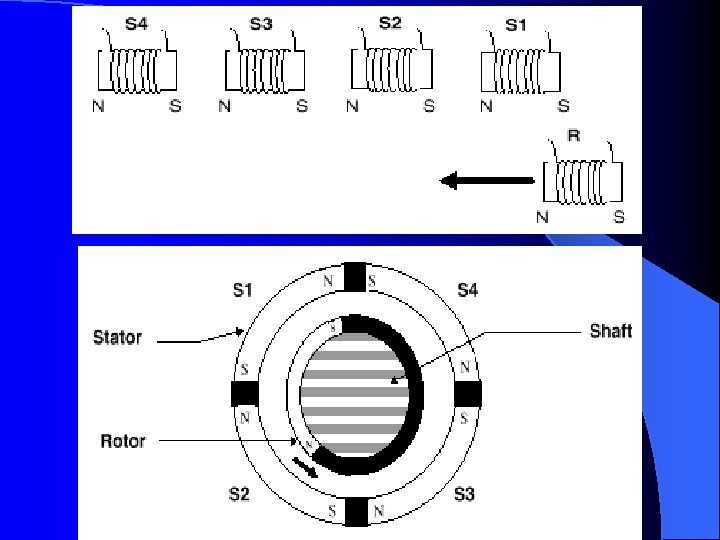
Operation of AC Motor
Operation of ac motor
Types of Induction motors ØSingle Phase Induction Motor ØPolyphase Induction Motor Single-phase Induction motors These motors are generally available upto 10 hp. The most common single phase motor types are: ØShaded pole, ØSplit phase ØCapacitor start
Shaded Pole Motor Have a continuous copper loop wound around a small portion of each pole. The loop causes the magnetic field through the ringed portion to lag behind the field in the unringed portion. This produces a slightly rotating field in each pole face sufficient to turn the rotor. As the rotor accelerates, its torque increases and rated speed is reached. Shaded pole motors have low starting torque. Slip is about 10%, or more at rated load
Split phase Motor uses both a starting and running winding. The starting winding is displaced 90 electrical degrees from the running winding. The current in the starting winding leads the current in the running winding, causing a rotating field. During startup, both windings are connected to the line. As the motor comes up to speed (at about 25% of full-load speed), a centrifugal switch actuated by the rotor, or an electronic switch, disconnects the starting winding. They have low or moderate starting torque and are limited to 1/3 hp.
Capacitor-start motor ØAre similar to split phase motors. The main difference is that a capacitor is placed in series with the auxiliary winding. This type of motor produces greater locked rotor and accelerating torque per ampere than split phase motor. Sizes range from fractional to 10 hp at 900 to 3600 rpm. They have an auxiliary winding with a capacitor, they produce a higher power factor. This makes them well suited to variable speed applications.
Polyphase Induction motor Squirrel cage Induction motors Ø Wound rotor induction motors Ø Squirrel cage Induction motors Most widely used due low cost & reliability Ø Simple construction, readily available Ø Easy to maintain Ø
Wound rotor Induction motor Used for Applications needing high starting torque, controlled starting torque & speed control Ø Rotor consists of 3 phase star winding internally Ø One end connected to 3 slip rings through mounted brushes Ø Starting torque can be increased by addition of resistance. Ø
Types of induction motor rotors
Motor terms and concepts current
Phase Torque curve of a motor
Horsepower Ø Motors & Engines are measured in horsepower Ø Standard unit of power used to measure the rate at which work is done. Ø One horsepower is equivalent of 550 footpounds per sec. Ø For example, if an electric motor can lift 550 pounds to 10 feet and takes 10 secs, then motor has a Horsepower rating of 1 HP.
Horsepower This formula will help us select the proper motor for a job. Notice the relationship between torque and speed. A 5 hp motor, designed to run at high speed, will have very little torque. To maintain the equation, torque must decrease as speed increases:
SPEED IS RELATED TO FREQUENCY and TORQUE IS RELATED TO CURRENT ØWe have seen that increasing the frequency at which the magnetic fields change will cause an increase in the speed of rotor. If the frequency were decreased, the motor speed would slow down. ØIf the current drawn by the stator and rotor is increased, this would cause a strengthening of the magnetic fields. This, in turn, would cause the torque generated by the motor to increase. ØLikewise, if the current were decreased, the torque would be decreased as well. In fact the horsepower formula can also be expressed in electrical terms of voltage and current, as:
Locked Rotor current
Synchronous speed = 120 F/P Synchronous speed is the speed of rotating magnetic field in induction motor
Motor Slip
Torque vs speed
Motor Cooling
Primary purpose of motor control Ø The locked Rotor Current / Inrush Current Ø Wear & Tear of the switchgears Ø When loads are started at full torque Ø Timing of motor stop
Variable Speed Drives
Variable Speed Drives Ø Most efficient speed control Ø Low maintenance, extended equipment life Ø Elimination of excessive inrush current Ø More flexibility Ø Energy savings Ø Solid state device, no moving parts contacts to wear out.
Air compressors with variable speed control
How variable speed drive works
Volts per Hertz ratio For example if the frequency is 60 Hz and the voltage is 460 V, then the volts per Hertz ratio (460 divided by 60) would be 7. 6 V/Hz. So, at half speed on a 460 V supplied system, the frequency would be 30 Hertz and the voltage applied to the motor would be 230 V and the ratio would still be maintained at 7. 6 V/Hz.
Constant Torque Loads Conveyors, hoists, drill presses, extruders, positive displacement pumps etc. Variable torque loads Require low torque at low speeds and higher torque at higher speeds such as fans, blower, propellers, centrifugal pumps. Fans and pumps are designed to make air or water flow. As the rate of flow increases, the water or air has a greater change in speed put into it by the fan or pump, increasing its inertia
Load is important for energy savings. The change in speed is equal to the horsepower cubed. For example, for a 50% change in speed would produce a 50% change in volume and would require 50% of the horsepower. But this 50% change in speed must be cubed, representing only 12. 5% of the horsepower required to run it at 100% speed. The reduction of horsepower means that it costs less to run the motor. When these savings are applied over yearly hours of operation, significant savings accumulate.
Relation between Speed, Torque & HP % Speed % Torque % HP 100 100 90 81 72. 9 80 64 51. 2 70 49 34. 3 60 36 21. 6 50 25 12. 5
Constant Horse Power Loads Ø Grinders, lathes, coil winders. The torque required for the load decreases as the speed increases or vice versa. Hence, the product of torque & speed, which is horsepower, is approx. constant as the speed changes. This type of loading is usually applied above base speed. For example, an empty reel winding a coil will require the least amount of torque initially and will be accelerated to the highest speed. As the coil builds up on the reel, the torque required will increase and the speed will be decreased.
What is Braking In an Electric Motor, once the load is in motion it has inertia and stays in motion. So, while we add energy to get the load into motion, we must somehow remove energy to stop it. Ø Some large motor loads develop high inertial forces when they are operating at high speed. If voltage is simply disconnected from the motor the load may coast for several minutes before the shaft comes to a full stop. Ø In applications such as those involving large saw blades and grinding wheels. It’s important for safety reasons to bring these loads to a smooth stop quickly. Ø In other load applications such as elevators and cranes, the location where the load stops is as important as moving the load. This means that the motor shaft must stop moving at a precise time to place the load at its proper location. Ø
Different types of Braking techniques DC braking DC current is applied to the stationary field of an AC motor when the stop button is depressed. Ø Since the field is fixed and it replaces the rotating stator field the rotor is quickly stopped by the alignment of the unlike magnetic fields between the rotating and stationary windings. Ø The attraction between the rotating and stationary fields is so strong that the rotor is stopped quickly. Ø
Dynamic braking when the voltage is removed from a motor and the inertia of the load continues on in motion the motor is being driven by the load until it coasts to a stop. Ø Since the rotor will continue to spin, it will produce voltage and current in a manner similar to a generator. This generator action can be used to bring the rotor to a quick stop by sending the generated energy out to a resistor. Ø There the energy is dissipated as heat through the resistor. The resistor will cause the rotor to generate very high levels of current, which produces magnetic forces on the shaft and causes it to stop quickly. Ø
DC Injection Ø DC injection applies DC power to an AC induction motor, which then produces a braking torque