Measurement of Inner Shape of Cavity ENAMI Kazuhiro


Distance Measurement (2 D)Shape Measurement")


- Slides: 19
Measurement of Inner Shape of Cavity ENAMI Kazuhiro Mechanical Engineering Center KEK
Purpose • To Measure Inner Macro Shape of Cavity Directly In accuracy of 0. 1 mm or higher from Iris to equator – Diameter, Coaxialty, Bending, Welding Bead etc – Errors in Production • Welding • Hidro. Forming – Deformation By • Welding • Polishing • Gravity
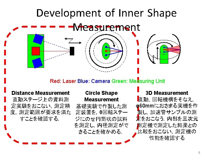
How to measure Inner Shape of a Cavity? (1 D)Distance Measurement (2 D)Shape Measurement Rotate a measuring Unit (3 D)Shape Measurement Slide a measuring Unit
Measurement Using Laser and Camera System • Laser-Camera Measurement can measure distance with 0. 01 mm resolution C Low Resolution A B C B High Resolution A Laser Point on Camera Image Laser (Point or Line) Camera (or PSD)
Difficulty in measurement of Inner Shape • To Measure distance with high resolution, following conditions are required – – – Long Distance between Laser and Camera Close to an Object Small Measureable Distance Good Camera and Lenz Good Surface Condition • To Measure shape with high resolution, following conditions are required • Accurate 3 -Dimensional Location of measuring unit • It is difficult to satisfy these conditions in measurement of inner shape
Downsizing of typical system • Down-sized Φ 80 mm Measurement Unit can measure distance only in 1 mm resolution ! C Low Resolution A B C B High Resolution A Laser Point on Camera Image Laser (Point or Line) Camera (or PSD) A B C
Solution of Problems • Image Processing – Break through CCD Pixels and Width of Laser Spot • • Error Canceling System using Multi Cameras Calibration of Distance Measurement Calibration of Shape Measurement Detection of 3 -Dimensional Position and Orientation of a Measuring Unit
Measuring Experiment using Image Processing and two Cameras 測定装置 9
Result Under Worst Conditions Left Camera Right Camera Resolution of Left Camera 0. 13 mm Resolution of Right Camera 0. 16 mm Zoom In Left Camera – Right Camera Resoluition 0. 064 mm Images Line Image is disturbed by Speckle Pattern 10
Calibration by Identification of Parameters • Original Point of Measuring Unit is different from Rotation axis • To measure correct shape, It is necessary to Identify vectors from Rotation axis to Origin of Measuring Unit (Sx, Sy) Nominal value l 11 θ (Sxcosθ-Sysinθ, Sxsinθ+Sycosθ) (lcosθ, lsinθ) Actual value (Sxcosθ-Sysinθ+lcosθ, Sxsinθ+Sycosθ+lsinθ)
• Parameter identification by Pipe Parameter Vector Artifact Measurement Measured Point li – Center of Pipe→Rotation Axis • (ax, ay) – Rotation Axis→Origin of Header • (sx, sy) • Observed value θi Si Axis of Rotation A S 0 O LASER r – Angle • Θ – Distance • l – Radius of a Pipe • r Object Non Linear Least Square method →Gauss-Newton Method 12
Measuring Unit • Φ 80× 50 mm • 180 g: Laser Left Camera Right Camera Rotation Stage 13
Measurement of Distance Measure a Distance to object on Linear Stage using Point Laser Relation between Position of Laser Image and Position of Object 14
Calibration using Pipe Artifact • Aluminum • Outer Diameter – φ220 mm • Hight 100 mm – Inner Diameter φ100 mm, Calibration Experiment φ150 mm, Without Setting in high accuracy φ200 mm 15
Error Elimination of Raw Data and Identification of Parameters ※These Points are not errors ! Elimination of Uncertain Data By Software Error Elimination By Human regular reflection Saturation or Vanish of Laser Image To Identify Parameters which fits these data to Circle Data of φ150 mm 16
Reconstruction of shape • Circle Shape Φ 150 mm errors Deformation of Raw Data are Correctly reconstructed! 17
Measurement of φ100 mm Pipe • Measurement of φ100 mm Pipe Elimination of Uncertain Data By Software Result : Radius 49. 9 mm. Center is (0. 3 mm, -1. 2 mm) Successfully Shape Measurement without setting in high accuracy 18
Conclusion • 1 D Measurement – High Resolution higher than 0. 1 mm • Image Processing • Error Canceling • 2 D Measurement Done – Calibration using Pipe Object • 3 D Measurement – Design and Production of Measuring Machine – Detection of 3 -Dimensional Position and Orientation of a Measuring Header NOW GOING