Chapter 5 Airfoils Wings and Other Aerodynamic Shapes


")
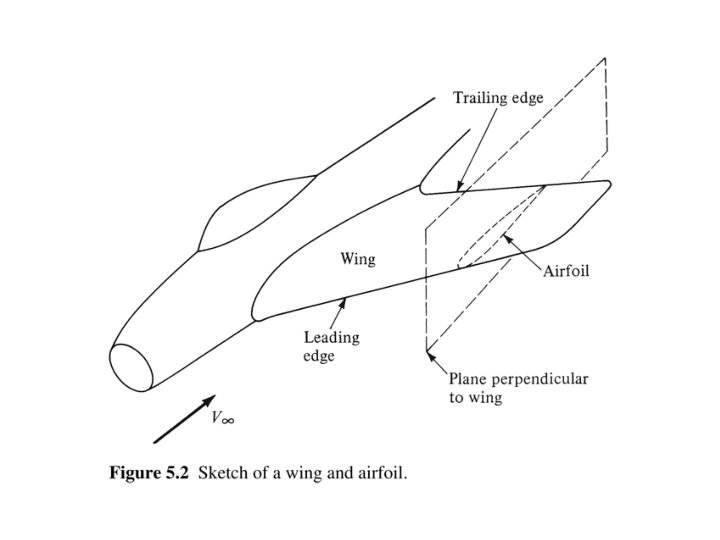
 Airfoil")


")
")
- Slides: 108
Chapter 5, Airfoils, Wings, and Other Aerodynamic Shapes – a mini course on aerodynamics Douglas S. Cairns Lysle A. Wood Distinguished Professor
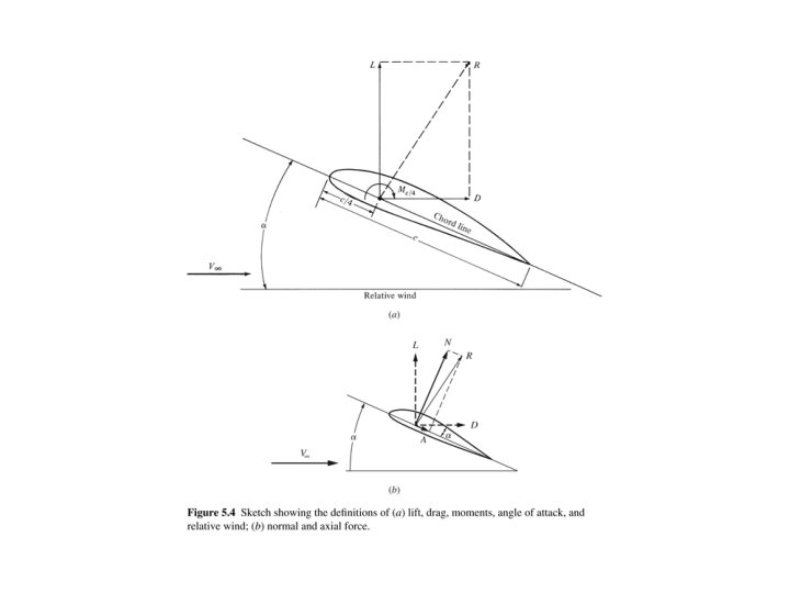
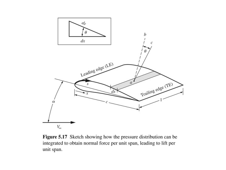
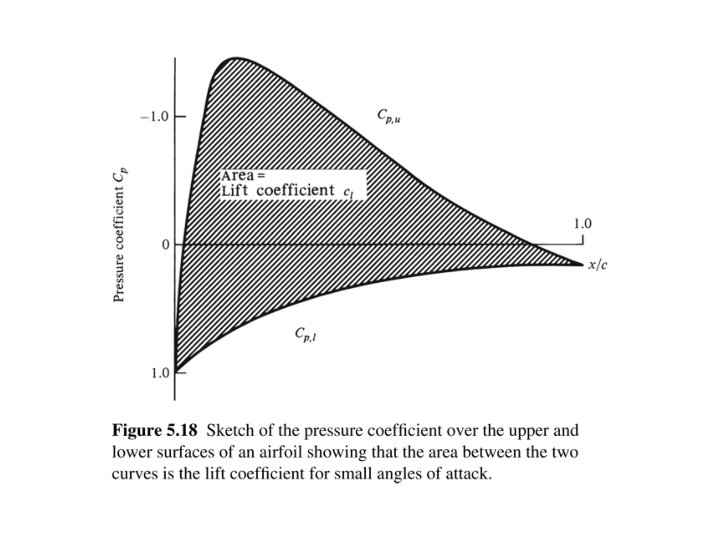
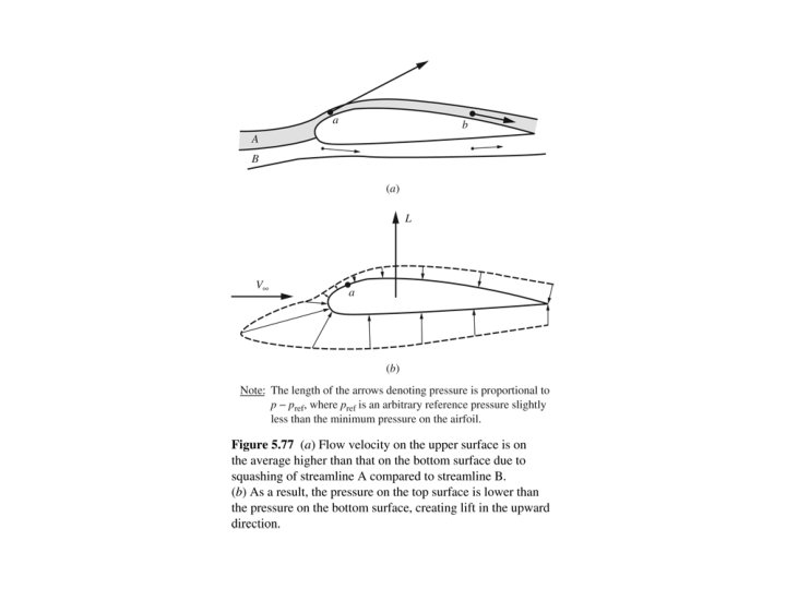
F 1 is the integrated resultant of pressure on the TOP surface F 2 is the integrated resultant of pressure on the BOTTOM surface
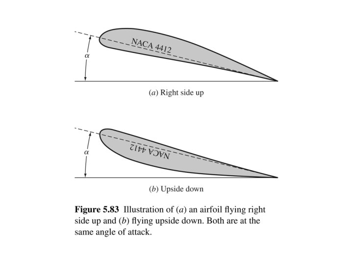
Note: The basis Cessna airfoil is a NACA 2412
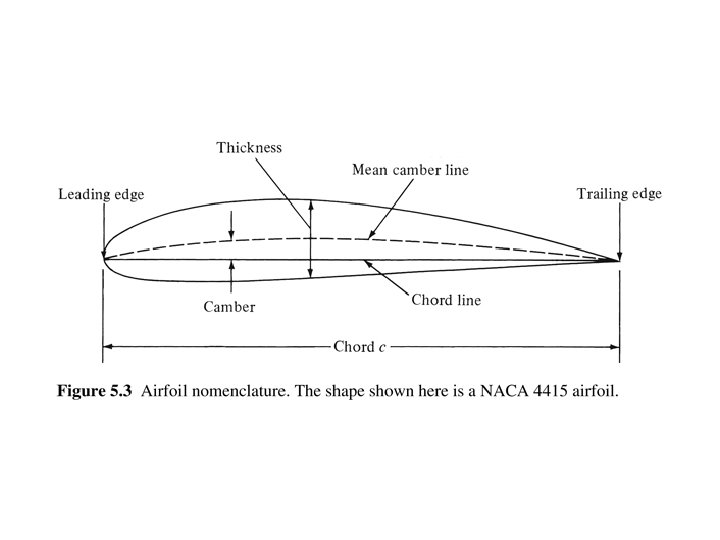
The NACA Airfoils The NACA airfoils are airfoil shapes for aircraft wings developed by the National Advisory Committee for Aeronautics (NACA). The shape of the NACA airfoils is described using a series of digits following the word "NACA. " The parameters in the numerical code can be entered into equations to precisely generate the cross-section of the airfoil and calculate its properties. "It shall be the duty of the advisory committee for aeronautics to supervise and direct the scientific study of the problems of flight with a view to their practical solution"
The first NACA Meeting - 1915
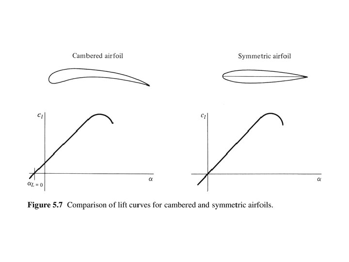
The NACA 4 Digit Series The NACA four-digit wing sections define the profile by: One digit describing maximum camber as percentage of the chord. One digit describing the distance of maximum camber from the airfoil leading edge in tens of percents of the chord. Two digits describing maximum thickness of the airfoil as percent of the chord. For example, the NACA 2412 airfoil has a maximum camber of 2% located 40% (0. 4 chords) from the leading edge with a maximum thickness of 12% of the chord. Four-digit series airfoils by default have maximum thickness at 30% of the chord (0. 3 chords) from the leading edge. The NACA 0015 airfoil is symmetrical, the 00 indicating that it has no camber. The 15 indicates that the airfoil has a 15% thickness to chord length ratio: it is 15% as thick as it is long.
The NACA 5 Digit Series The NACA five-digit series describes more complex airfoil shapes: The first digit, when multiplied by 0. 15, gives the designed coefficient of lift (CL). Second and third digits, when divided by 2, give p, the distance of maximum camber from the leading edge (as per cent of chord). Fourth and fifth digits give the maximum thickness of the airfoil (as per cent of the chord). For example, the NACA 12018 airfoil would give an airfoil with maximum thickness of 18% chord, maximum camber located at 10% chord, with a lift coefficient of 0. 15
Appendix D - NACA 2412 Airfoil
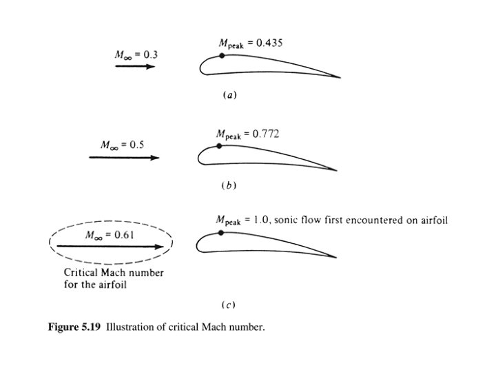
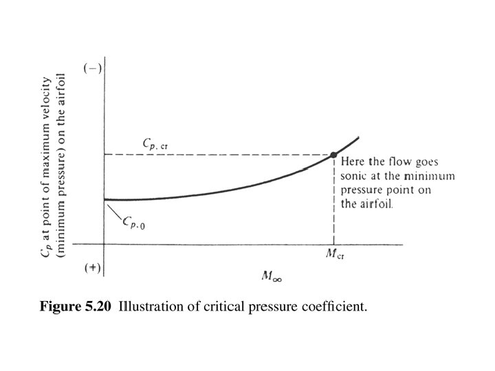
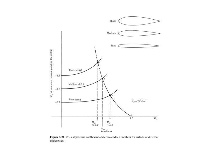
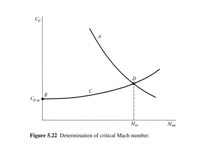
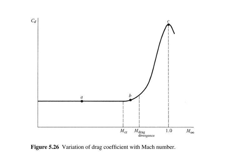
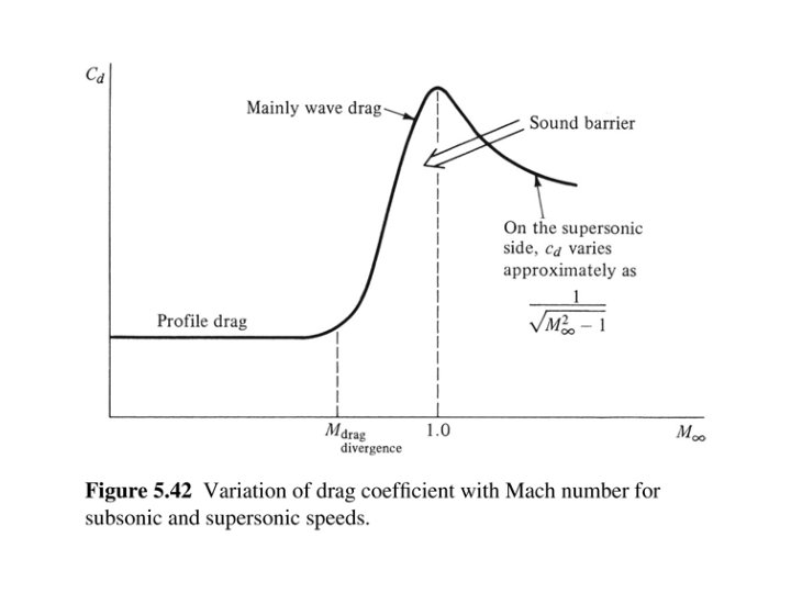
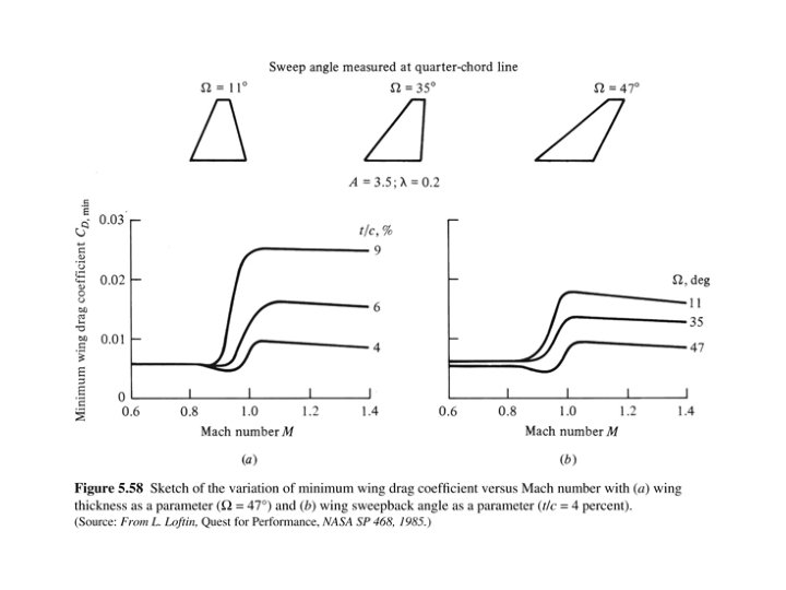
Summary Equations – Critical Mach Number and Compressibility (based on isentropic equations)
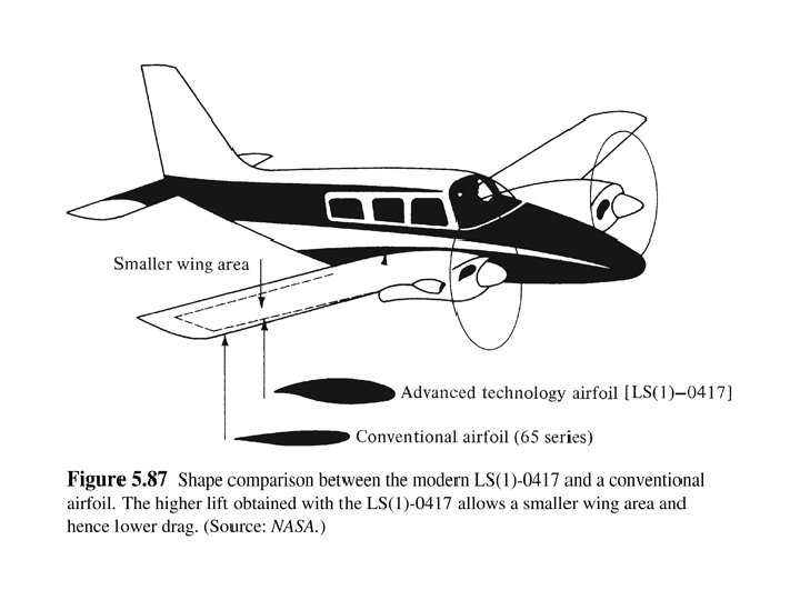
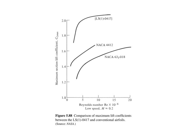
NASA LS (1) Airfoil
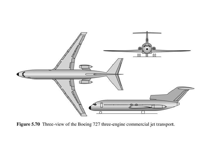
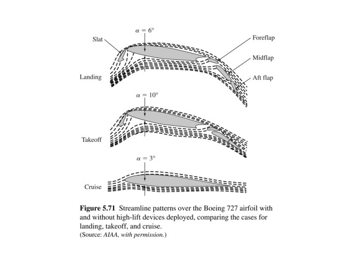
Boeing 737 Wing In flight, high lift devices retracted, configured for cruise, top picture with relatively new winglets Landing configuration, slats, flaps, and spoilers deployed (bottom)
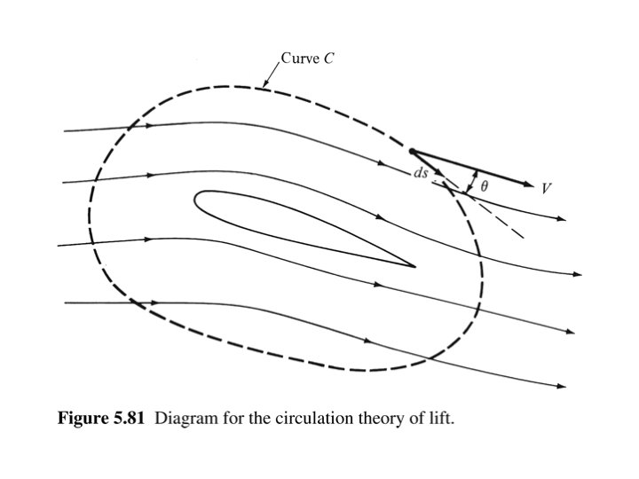
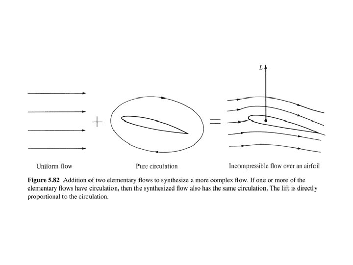
Circulation “Sails” Bureau Mauric ALCYONE Cousteau Society Calypso II; designed but not built Blowers are mounted at base to add circulation to free stream wind; creates lift leading to propulsion of the vessel
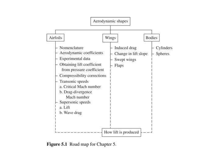
Chapter 5 Summary
Chapter 5 Summary (cont. )
Chapter 5 (cont. )